EasyManuals Logo

PerkinElmer LAMBDA 265 Installation Instructions

PerkinElmer LAMBDA 265
32 pages
To Next Page IconTo Next Page
To Previous Page IconTo Previous Page
Page #9 background imageLoading...
Page #9 background image
09931228D
9
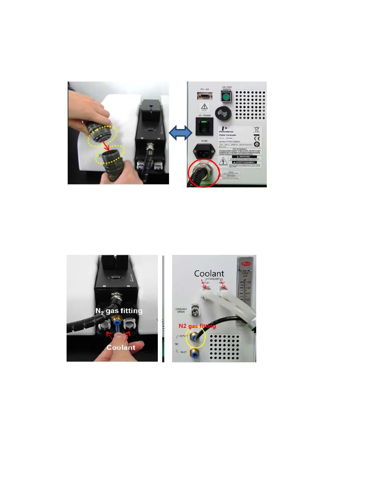
6. Connect the accessory interface cable of the Peltier controller to the interface connector of the
Peltier controlled single cell.
Figure 8 Connecting the accessory interface cable of the Peltier Controller to the
interface connector
7. Connect the coolant inlet/outlet and N
2
gas tube between the Peltier controller and the Peltier
controlled single cell.
Note:
N
2
gas is not always required [Tube for N
2
gas is not supplied].
Figure 9 Connecting the coolant inlet/outlet and N
2
gas tube
8. Connect the power cord and communication cable to the ports located at the rear of the Lambda
265.

Other manuals for PerkinElmer LAMBDA 265

Questions and Answers:

Question and Answer IconNeed help?

Do you have a question about the PerkinElmer LAMBDA 265 and is the answer not in the manual?

PerkinElmer LAMBDA 265 Specifications

General IconGeneral
BrandPerkinElmer
ModelLAMBDA 265
CategoryMeasuring Instruments
LanguageEnglish

Related product manuals