Chapter 4 35943
Page 28
How to set the valve tip clearances
Notes:
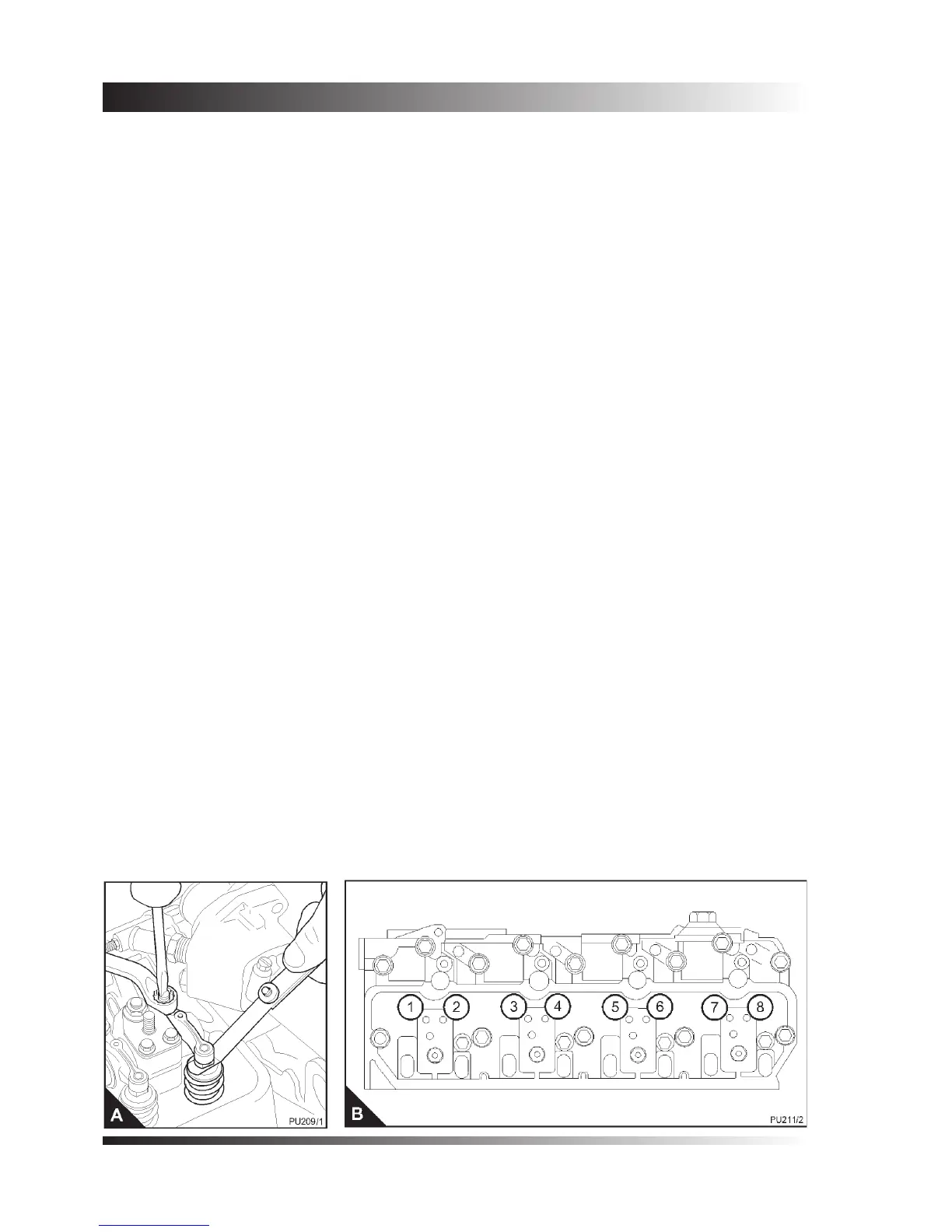
• The valve tip clearance is checked with a feeler gauge between the top of the valve stem and the rocker
lever (A), with the engine cold. The correct clearance for both the inlet and the exhaust valves is 0,35 mm
(0.014 in).
• The arrangement of the valves is shown in (B). Valve numbers (B1) and (B2) are for number 1 cylinder
which is at the front of the engine.
• Clockwise rotation is when seen from the front of the engine.
1. Disconnect the breather pipe from the rocker cover and remove the three cap nuts, steel washers and
rubber seals. Lift off the rocker cover.
2. Rotate the crankshaft in a clockwise direction until the valve (B7) has just opened and the valve (B8) has
not closed completely. Check the clearances of the valves (B1) and (B2) and adjust them, if necessary.
3. Rotate the crankshaft in a clockwise direction until the valve (B3) has just opened and the valve (B4) has
not closed completely. Check the clearances of the valves (B5) and (B6) and adjust them, if necessary.
4. Rotate the crankshaft in a clockwise direction until the valve (B1) has just opened and the valve (B2) has
not closed completely. Check the clearances of the valves (B7) and (B8) and adjust them, if necessary.
5. Rotate the crankshaft in a clockwise direction until the valve (B5) has just opened and the valve (B6) has
not closed completely. Check the clearances of the valves (B3) and (B4) and adjust them, if necessary.
Caution: If the outer cap nuts for the rocker cover are overtightened, the stud and plate assembly for the
rocker pedestal may be damaged.
6. Fit the rocker cover. Ensure that the cap nuts, washers and the rubber seals are tted correctly. Tighten
the cap nuts to 11 Nm (8 lbf ft) 1,1 kgf m. Fit the breather pipe.