16 SEBU8191-01
Product Information Section
Model Views
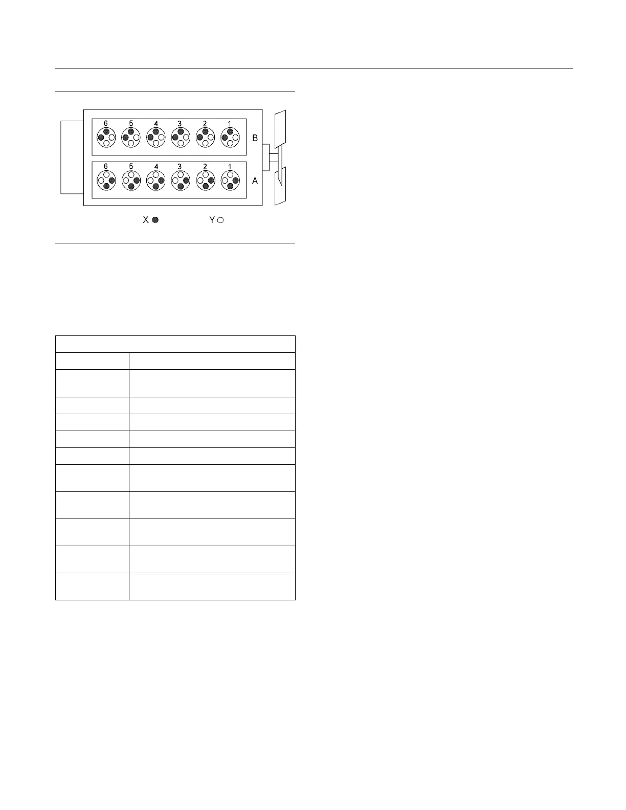
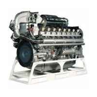
g01210840
Illustration 12
4012-46A Engine m odel
(A) Bank
(B) Bank
(X) Inlet valv es
(Y) Exhaust valves
Table 1
4012-46A Engine Specifications
Cycle 4 Stroke
Number of
Cylinders
12
Configuration Vee-form
Bore 160 mm (6.299 inch)
Strok
e
190 mm
(7.480 inch)
Displacement
45.84 L (2797.328 in
3
)
Compression
Ratio
13:1
Rotation
(flywheel end)
Counterclockwise
Firing Order
1A-6B-5A-2B-3A-4B-6A-1B-2A-
5B-4A-3B
Inlet Valve Lash
(Cold)
0.40 mm (0.016 inch)
Exhaust Valve
Lash (Cold)
0.40 mm (0.016 inch)
Engine Cool ing and Lubrication
The cooling system consists of the following
components:
•
Gear-driven water pumps
•
Water temperature regulators which regulate the
engine coolant temperature
•
Gear-driven oil pump (gear type)
•
Oil coolers
The engine lubr
icating oil is supplied by a gear-driven
pump. The lubrication oil is cooled and filtered.
Bypass valves provide unrestricted flow of lubrication
oil to the engi
nepartswhenoilviscosityishigh.
Bypass valves can also provide unrestricted flow
of lubrication oil to the engine parts if the oil fi lter
element shou
ld become plugged.
Engine efficiency, efficiency of emission controls, and
engine perf
ormance depend on adherence to proper
operation and maintenance recommendations.
Engine performance and efficiency also depend on
the use of re
commended fuels, lubrication oils, and
coolants. Refer to this Operation and Maintenance
Manual, “Maintenance Interval Schedule” for more
informati
on on maintenance items.