N39453 Chapter 3
Page 37
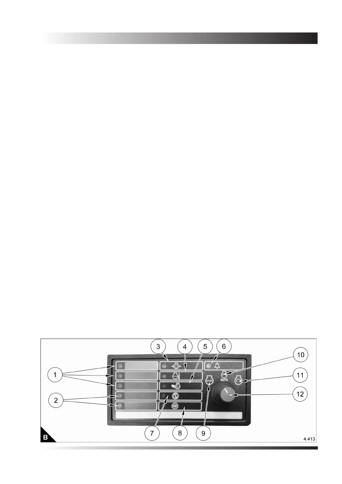
Control module (optional)
The control panel (B) has six indicators (B3 to B8) that correspond to certain fault conditions. An indicator
illuminates when the corresponding problem exists. Each indicator has a label that identies the problem. The
Engine Control Switch (B12) must be turned to the OFF/RESET position (B9) in order to turn off the indicators
and to reset the control panel. The panel also incorporates two spare indicators.
Programmable indicators (B1)
The control panel is programmed in order to alert the operator to various conditions, ie - Engine Running, Not
in Auto and Emergency Stop
Note: See separate manual supplied with the unit.
Indicators (B2)
These are not used.
Indicator for the oil pressure (B3)
This indicates when the engine oil pressure has fallen below the low limit of the oil pressure switch.
Indicator for the coolant temperature (B4)
This lights when the engine water temperature has risen above the upper limit of the water temperature
switch.
Indicator for engine overspeed (B5)
This lights when the control board detects that the engine speed has exceeded the overspeed set point.
Indicator for the alarm (B6)
This indicator lights as a warning when the control module has received any signals that have been programmed
to light with the alarm. When the indicator ashes, there is a shut down fault.
Indicator for engine overcrank (B7)
This lights when the engine fails to start due to the limit for cranking being exceeded.
Indicator for emergency stop (B8)
This lights when the stop push button has been pressed.
Stop/Reset position (B9)
When the Engine Control Switch (B12) is in this position, the fault indicators are reset and the engine shuts
down immediately.
Automatic start position (B10)
When the Engine Control Switch (B12) is in this position, the engine will start automatically when the remote
initiate contact is closed or will shutdown when opened.
Manual start position (B11)
When the Engine Control Switch (B12) is in this position, the engine will start and will continue to run until the
position is changed.
Engine control switch (B12)
This selects Automatic or Manual starting and off and reset options.