13
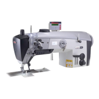
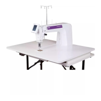
Stand and table top
8087
70
31
47,5
121,5
322,5
562,5
595,5
90
512
35
285
283
190
70
±0,5
35
131
44
128
±0,3
135
136
165
128
±0,3
156
20,8
250
Ø14
0/1
370
80
260
47
15
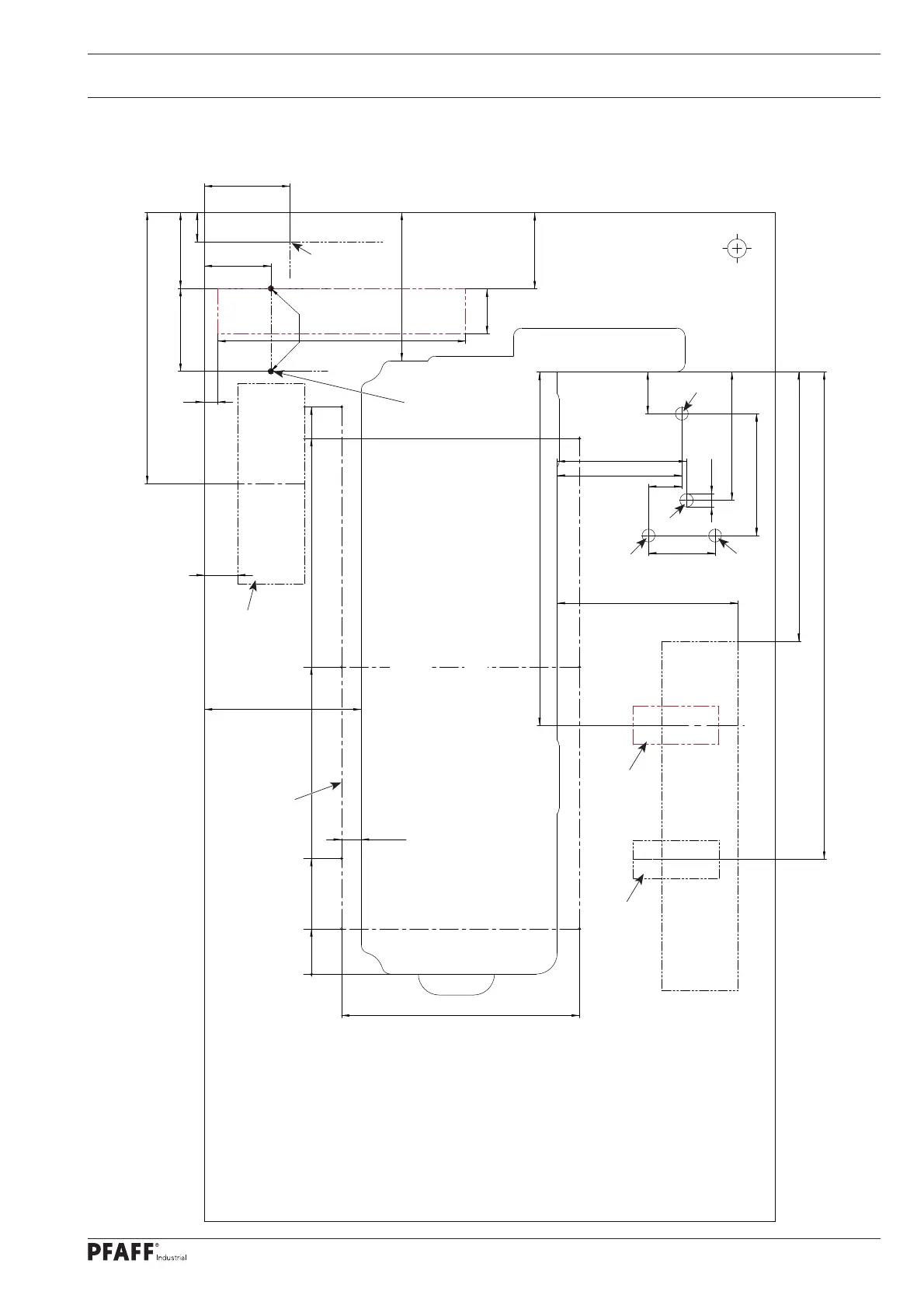
3.02 Assembly drawing for the table
3
.02.01 On machines with 350 mm clearance width
Speedcontrolunit
P45 / P74
View:
Underside table top
Stand position
906-3750-010/895
Controlbox
P45 / P74
= Drillholes for fastening the motor
(Screwed inserts M8 x 30 )
= Hole for the sewing head support
= Öl pan
= Holes for main switch (P45 PD + P74 ED)
= Braeket for drawer
Controlbox
AB 321 + PF 321
Speedcontrolunit
AB 321 + PF 321
 Loading...