Service Modes, Error Codes, and Fault Finding
EN 20 LC9.3L LA5.
2010-Mar-26
5.3 Service Tools
5.3.1 ComPair
Introduction
ComPair (Computer Aided Repair) is a Service tool for Philips
Consumer Lifestyle products. and offers the following:
1. ComPair helps you to quickly get an understanding on how
to repair the chassis in a short and effective way.
2. ComPair allows very detailed diagnostics and is therefore
capable of accurately indicating problem areas. You do not
have to know anything about I2C or UART commands
yourself, because ComPair takes care of this.
3. ComPair speeds up the repair time since it can
automatically communicate with the chassis (when the uP
is working) and all repair information is directly available.
4. ComPair features TV software up possibilities.
Specifications
ComPair consists of a Windows based fault finding program
and an interface box between PC and the (defective) product.
The (new) ComPair II interface box is connected to the PC via
an USB cable. For the TV chassis, the ComPair interface box
and the TV communicate via a bi-directional cable via the
service connector(s).
How to Connect
This is described in the ComPair chassis fault finding database.
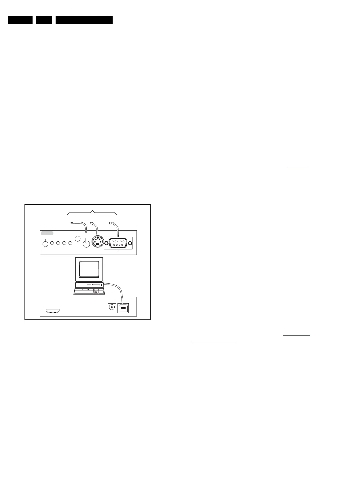
Figure 5-3 ComPair II interface connection
Caution: It is compulsory to connect the TV to the PC as
shown in the picture above (with the ComPair interface in
between), as the ComPair interface acts as a level shifter. If
one connects the TV directly to the PC (via UART), ICs will be
blown!
How to Order
ComPair II order codes:
• ComPair II interface: 3122 785 91020.
• ComPair UART interface cable: 3138 188 75051.
• Program software can be downloaded from the Philips
Service portal.
Note: If you encounter any problems, contact your local
support desk.
5.4 Error Codes
5.4.1 Introduction
The error code buffer contains all detected errors since the last
time the buffer was erased. The buffer is written from left to
right, new errors are logged at the left side, and all other errors
shift one position to the right.
When an error occurs, it is added to the list of errors, provided
the list is not full. When an error occurs and the error buffer is
full, then the new error is not added, and the error buffer stays
intact (history is maintained).
To prevent that an occasional error stays in the list forever, the
error is removed from the list after more than 50 hrs. of
operation.
When multiple errors occur (errors occurred within a short time
span), there is a high probability that there is some relation
between them.
New in this chassis is the way errors are displayed:
• There is a simple blinking LED procedure for board level
repair (home repair) so called LAYER 1 errors, next to the
existing errors which are LAYER 2 errors (see Table 5-3
).
– LAYER 1 errors are one digit errors (via CSM).
– LAYER 2 errors are 2 digit errors (via SAM/SDM).
• In protection mode:
– From consumer mode: LAYER 1.
– From SDM mode: LAYER 2.
• In CSM mode: When entering CSM: error LAYER 1 will be
displayed by blinking LED. Only the latest error is shown.
• In SDM mode: When SDM is entered via Remote Control
code or the hardware pins, LAYER 2 is displayed via
blinking LED.
• In the “ON” state: with the RC commands “mute_06250X
_OK”, LAYER 2 errors are displayed via blinking LED.
• Error display on screen:
– In CSM no error codes are displayed on screen.
– In SAM the complete error list is shown.
5.4.2 How to Read the Error Buffer
Use one of the following methods:
• On screen via the SAM (only when a picture is visible).
E.g.:
– 00 00 00 00 00: No errors detected
– 23 00 00 00 00: Error code 23 is the last and only
detected error.
– 37 23 00 00 00: Error code 23 was first detected and
error code 37 is the last detected error.
– Note that no protection errors can be logged in the
error buffer.
• Via the blinking LED procedure. See section 5.4.3 How to
Clear the Error Buffer.
•Via ComPair.
5.4.3 How to Clear the Error Buffer
Use one of the following methods:
• By activation of the “Reset error buffer” command in the
SAM menu.
• With a normal RC, key in sequence “MUTE” followed by
“062599” and “OK”.
• If the content of the error buffer has not changed for 50+
hours, it resets automatically.
10000_036_090121.eps
091118
TO
UART SERVICE
CONNECTOR
TO
UART SERVICE
CONNECTOR
TO
I
2
C SERVICE
CONNECTOR
TO TV
PC
HDMI
I
2
C only
Optional power
5V DC
ComPair II Developed by Philips Brugge
RC out
RC in
Optional
Switch
Power ModeLink/
Activity
I
2
C
ComPair II
Multi
function
RS232 /UART