Below are a few more comments.
Motor:
The distance between rotor and stator is approx. 0.2 mm, so that the rotor can be centered with small
shims of that size.
Pick-up arm:
The pick-up arm is clamped to the hollow shaft of the caliper spring/steering hook with the clamping
bracket (93) FIG 8 .
Pick-up bearing:
By removing the adjusting ring (90) FIG 8., the entire steering hook can be removed. Watch out
for the bearing balls and also the spacer falls out 70 FIG 8
Platen-printer:
By loosening the fastening screws at the foot of the disc-press/plate presser, it can be removed. After
removal of the clamping ring (103) FIG 8, the guide rod can be pushed out of the ball bush.
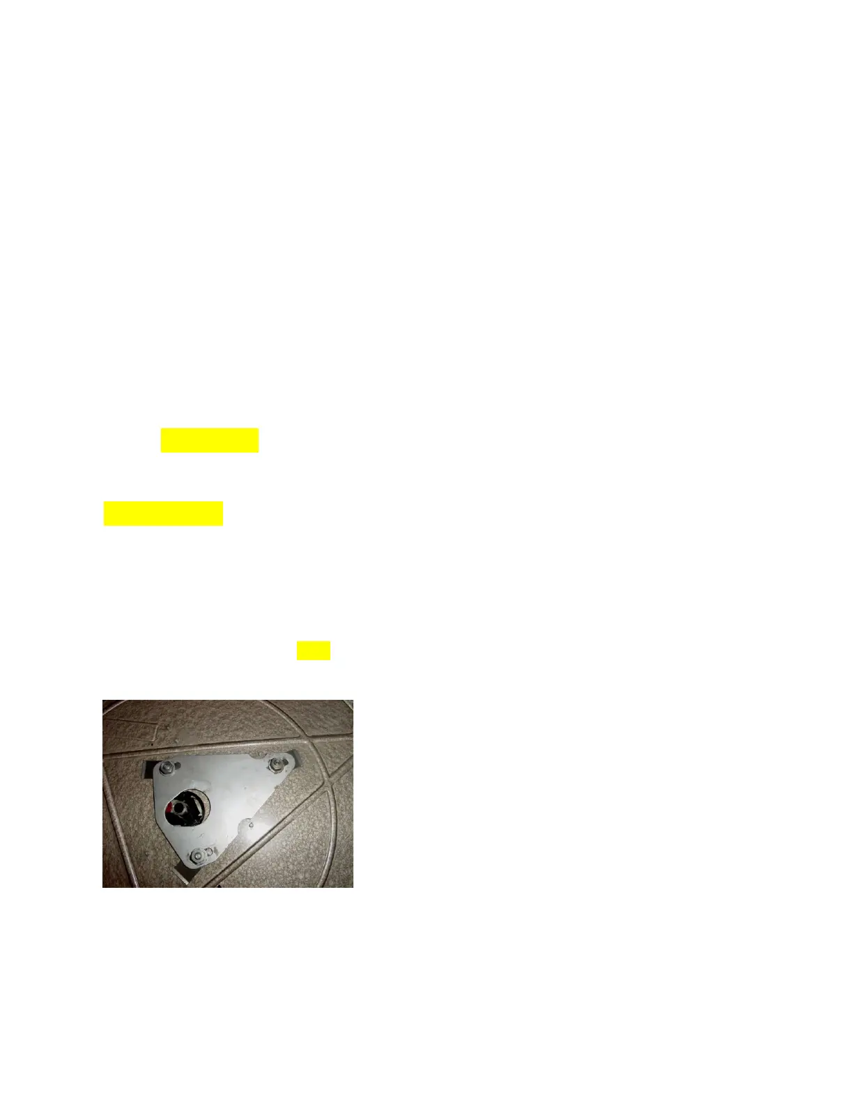
Mechanism:
After removal of the turntable (C clip/clamping ring 64) FIG 8, the entire mechanism can be removed by
removing the 3 nuts.
In advance, the various connections must first be disconnected. The top plate (N fig. 8) can be moved in
the direction of the main axis/ shaft thanks to the oblong/slotted holes. In order to prevent deformation
of the main axis, when the platform is pressed, the distance between main axis and plate must be as
small as possible.
25