4. The change spindle pins; for adjustment
5. Motor parts.
6. Start-stop mechanism
7. Speed control
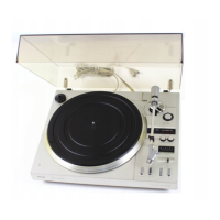
8. The mechanism [ HET MECHANISME]
…………………………………
9. CONTROL DISC/Command disc and steering hooks
‘’’’’’’’’’’’’’’’’’’’’’’’’’’’’’’’’’’’’’’’’’’’’’’’’’’’’’’’’’’’’’’’’’’’’’’’’’’’’’’’’’’’’’’’’’’’’’’’’’’’’’’’’’’
IV. Connection and electrical data.
The mains cable must be connected to the two bottom connection points on the motor switch plate
(fig.1).
From both figures A and B (fig.1). it is easy to see how switching from 110 to 220V and vice versa
can be performed.
To connect to a different mains frequency 60/50/40hz, it is necessary to fit a different pulley (1) on the
shaft of the motor. NO LONGER AVAILABLE [I had mine reduced/machined locally in 3 20% steps for
60hz operation]
These pulleys are included in the parts list, stating the mains frequency for which they are intended.
When another pulley is applied, the number of turns of the plate must be adjusted
again, as indicated in IX-8. USE A STROBE
Connection of the P.U. unit takes place in the sealed junction box, which is mounted below the
mounting plate. The shielding of the P.U. cable is connected to the middle soldering lip (fig.2). Parallel to
the P.U. terminal, a resistor (R1 - FIG. 2) of 0.47 M ohm is connected for good adjustment of the
crystal P.U. unit.
[I added a MONO-RCA plug/jack pigtail.]
9