User Manual BDL3215E / BDL4225E
9
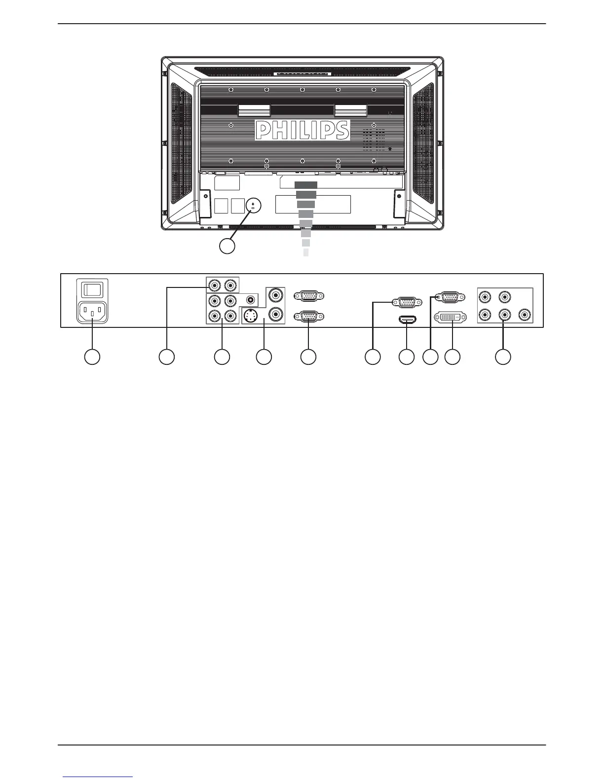
Terminal Panel
(OUT)
1 3 4 5
11
72 6 9 108
(IN)
(OUT)
(IN)
a AC IN connector
Connect the supplied power cord to the wall outlet.
b AUDIO OUT
To output the audio signal from AUDIO IN 1, 2, or 3 jack to
an external device (Stereo receiver, amplifier, etc.).
c AUDIO IN 1, 2, 3
To input audio signal from an external equipment such as
computers, VCRs, or DVD players.
d VIDEO INPUT/OUTPUT Connector
VIDEO IN connector (BNC): v To input composite
video signal.
VIDEO OUT connector (BNC):v To output
composite video signal from VIDEO IN connector.
S-VIDEO IN connector (Mini DIN 4 pin):v To input
S-VIDEO (Y/C separate signal).
e EXTERNAL CONTROL (D-Sub 9 pin)
Connect RS-232C input from external equipment such as
computers for the use of loop through function.
f VGA OUT (mini D-Sub 15 pin)
To output the signal from VGA IN and RGB component.
g HDMI IN
Connecting equipment such as DVD players, HDTV devices,
or Set-Top-Box.
h VGA IN (mini D-sub 15 pin)
To input analog RGB signals from a computer or from other
RGB equipment.
i DVI-D INPUT
To input digital RGB signals from a computer or other HDTV
device with digital RGB output.
* This connector does not support analog input.
j VGA (BNC) [R, G, B, H, V] or COMPONENT [Y, Cb/
Pb, Cr/Pr]
To input analog RGB or Y, Cb/Pb,Cr/Pr signals from DVD
players, HDTV decoders, set-top-box or game consoles etc.
k Kensington Lock
For security and theft prevention.