User Manual BDS4223V
19
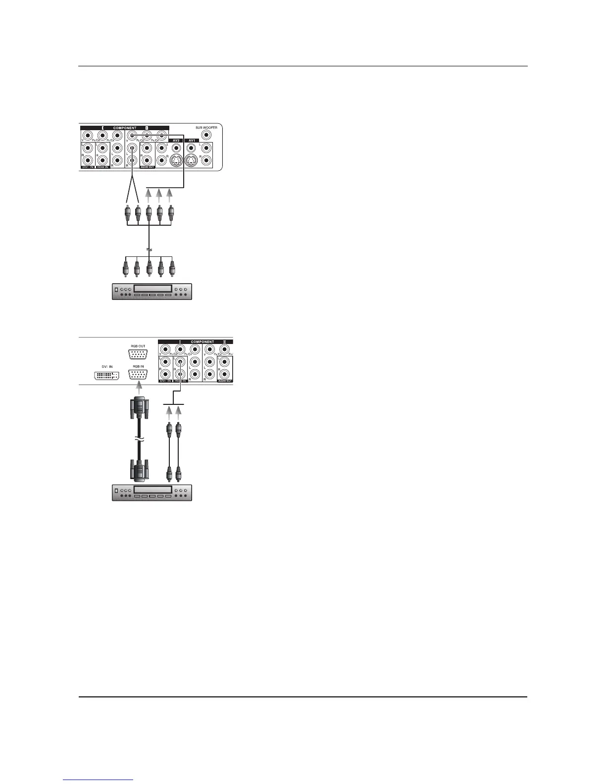
5.3 CONNECTING A HDTV DECODER SET-TOP
BOX
Using Component Video Input
1 Connect the green (labeled as "Y") jack from the HDTV Set-top box
to the green "Y1" jack of the monitor.
2 Connect the red (labeled as "PR" or "CR") jack from the HDTV Set-
top box to the red "PR1/CR1" jack of the monitor.
3 Connect the blue (labeled as "PB" or "CB") jack from the HDTV Set-
top box to the blue "PB1/CB1" jack of the monitor.
4 Connect the red (R) and white (L) audio jacks from the HDTV Set-
top box to the R and L audio-in jacks located next to the "PR1/CR1"
connector.
Note:
Some HDTV Set top boxes may not have a Component Video output.
Instead, use RGB input method.
Using RGB Input
1 Connect the 15-pin D-Sub RGB connector from the back of the
HDTV Set-top box to the RGB-IN Connector located on the back of
the monitor.
2 Connect the red (R) and white (L) audio-out jacks from the HDTV
Set-top box to the R and L audio-in jacks located to the left of the
S-VIDEO connector.
Notes:
■ Some HDTV Set-top boxes may not have a RGB output. Use the
Component Video input method if this is the case.
■ Upon connecting your HDTV Set-top box to the RGB input of the
monitor, it may be necessary to adjust various picture settings on the
monitor to correctly match the output of the HDTV Set-top box.
This is caused by the different video timings set by various HDTV
Set-top box manufacturers.
Component Video
(3xRCA cable)
Audio L/R
(2xRCA cables)
HDTE SET-TOP BOX
Audio L/R
(2xRCA cables)
RGB cable
(15 Pin D-Sub)
HDTV SET-TOP BOX