1-8-2 E9480DC
Note:
(1): Identification (location) No. of parts in the figures
(2): Name of the part
(3): Figure Number for reference
(4): Identification of parts to be removed, unhooked,
unlocked, released, unplugged, unclamped, or
desoldered.
P=Spring, L=Locking Tab, S=Screw,
CN=Connector
*=Unhook, Unlock, Release, Unplug, or Desolder
e.g. 6(S-1) = six Screws (S-1),
5(L-1) = five Locking Tabs (L-1)
(5): Refer to “Reference Notes.”
Reference Notes
CAUTION 1: Locking Tabs (L-1), (L-2) and (L-3) are
fragile. Be careful not to break them.
1-1. Connect the wall plug to an AC outlet and press
the [OPEN/CLOSE] button to open the tray.
1-2. Remove the Tray Panel by releasing two locking
tabs (L-1).
1-3. Press the [OPEN/CLOSE] button again to close
the tray.
1-4. Press the [POWER] button to turn the power off.
1-5. Unplug the AC cord.
1-6. Disconnect connectors CN204 and CN205.
1-7. Release five Locking Tabs (L-2). Then release
three Locking Tabs (L-3), and remove the Front
Unit.
2. When reassembling, solder wire jumpers as shown
in Fig. D8.
3. Before installing the Deck Assembly, be sure to
place the pin of LD-SW on Main CBA as shown in
Fig. D8. Then, install the Deck Assembly while
aligning the hole of Cam Gear with the pin of LD-
SW, the shaft of Cam Gear with the hole of LD-SW
as shown in Fig. D8.
[18]
Deck
Assembly
D8
(S-22), (S-23),
Desolder
2
3
[19]
Function
CBA
D8 Desolder ---
[20] Main CBA D8 ---------- ---
[21]
CPU CBA
Unit
D8
4(S-24), *CN215,
*CN216
---
[22]
Deck
Pedestal
D9 8(S-25) ---
[23]
Front
Bracket R
D9
(S-26), 2(S-27),
iLink Cable [ A ]
---
↓
(1)
↓
(2)
↓
(3)
↓
(4)
↓
(5)
ID/
LOC.
No.
PART
REMOVAL
Fig.
No.
REMOVE/*UNHOOK/
UNLOCK/RELEASE/
UNPLUG/DESOLDER
Note
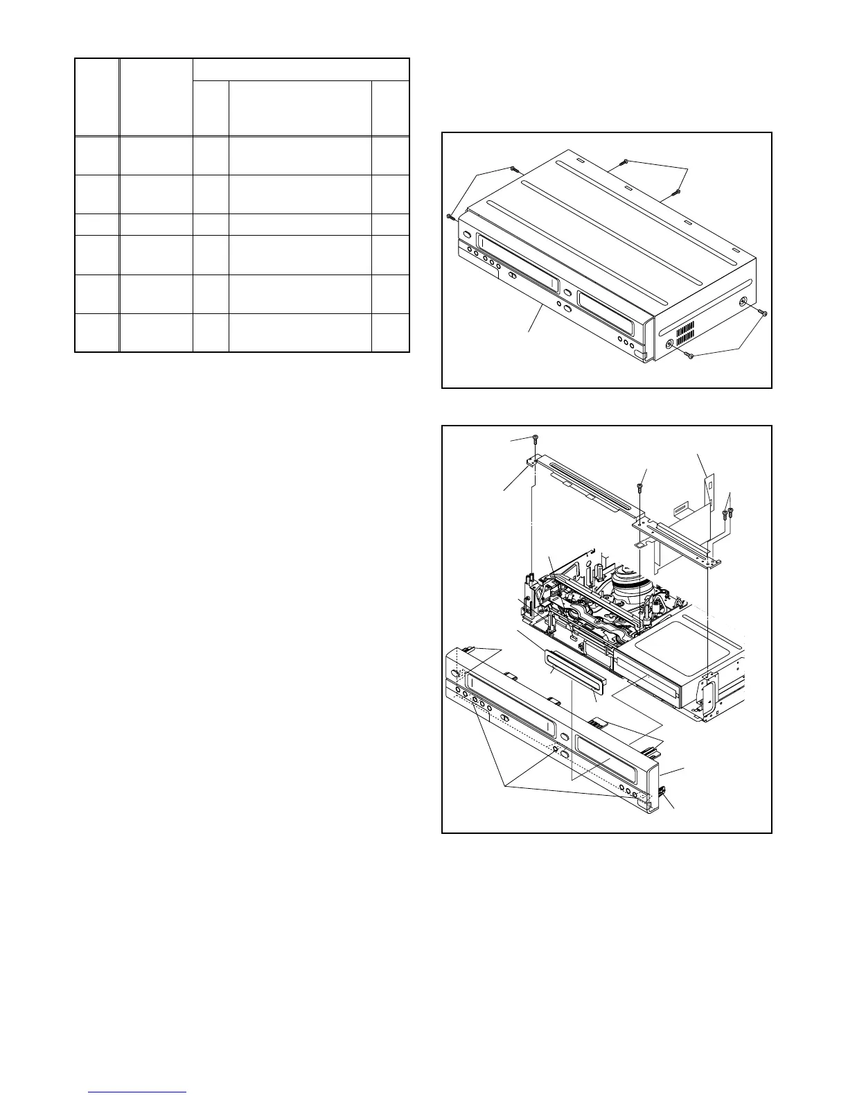
(S-1)
(S-1)
(S-1)
[1] Top Cover
Fig. D1
(L-2)
Trya Panel
CN205
CN204
(L-2)
[2] Front
Assembly
[3] Front
Bracket
[4] Radiation Sheet
(L-2)
(L-1)
(L-1)
Fig. D2
(L-3)
(S-2)
(S-2)
(S-3)