1-12-35
1-12-36
E9480SCM8
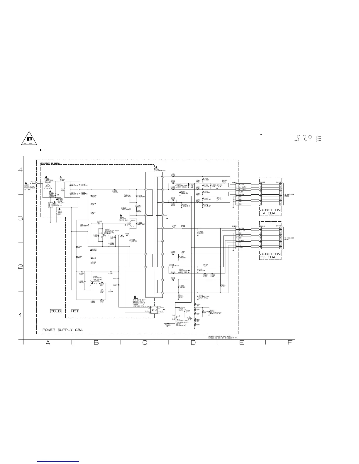
Power Supply Schematic Diagram < VCR Section >
NOTE :
The voltage for parts in hot circuit is measured using
hot GND as a common terminal.
A V
F
CAUTION
FOR CONTINUED PROTECTION AGAINST FIRE HAZARD,
REPLACE ONLY WITH THE SAME TYPE FUSE.
ATTENTION : POUR UNE PROTECTION CONTINUE LES RISQES
D'INCELE N'UTILISER QUE DES FUSIBLE DE MÊME TYPE.
RISK OF FIRE-REPLACE FUSE AS MARKED.
"This symbol means fast operating fuse."
"Ce symbole reprèsente un fusible à fusion rapide."
CAUTION !
Fixed voltage ( or Auto voltage selectable ) power supply circuit is used in this unit.
If Main Fuse (F1001) is blown, check to see that all components in the power supply
circuit are not defective before you connect the AC plug to the AC power supply.
Otherwise it may cause some components in the power supply circuit to fail.
“ “ = SMD
Voltage indications for PLAY, REC and DVD modes
on the Schematic Diagrams are as shown below:
1 2 3
5.0
(2.5)
<
0
>
~
5.0
THE SAME VOLTAGE FOR
PLAY,REC & DVD MODES.
INDICATES THAT THE VOLTAGE
IS NOT CONSISTENT HERE.
PLAY MODE
REC MODE
DVD MODE