1-12-1 SC_01
SCHEMATIC DIAGRAMS / CBA’S AND TEST POINTS
Standard Notes
WARNING
Critical components having special safety characteris-
tics are identified with a # by the Ref. No. in the parts
list and enclosed within a broken line (where several
critical components are grouped in one area) along
with the safety symbol # on the schematics or
exploded views.
Use of substitute replacement parts which do not have
the same specified safety characteristics may create
shock, fire or other hazards.
Under no circumstances should the original design be
modified or altered without written permission from
Philips Consumer Electronics Company. Philips
assumes no liability, express or implied, arising out of
any unauthorized modification of design. Servicer
assumes all liability.
* Broken Line :
Capacitor Temperature Markings
Capacitors and transistors are represented by the fol-
lowing symbols.
Notes:
1. Do not use the part number shown on these draw-
ings for ordering. The correct part number is shown
in the parts list, and may be slightly different or
amended since these drawings were prepared.
2. To maintain original function and reliability of
repaired units, use only original replacement parts
which are listed with their part numbers in the parts
list section of the service manual.
3. How to read converged lines.
Examples:
(1). "1-D3" means that line number "1" goes to area
"D3."
(2). "1-B1" means that line number "1" goes to area
"B1."
4. All resistance values are indicated in ohms
(K=10
3
, M=10
6
).
5. Resistor wattages are 1/4W or 1/6W unless other-
wise specified.
6. All capacitance values are indicated in µF
(P=10
-6
µF).
7. All voltages are DC voltages unless otherwise
specified.
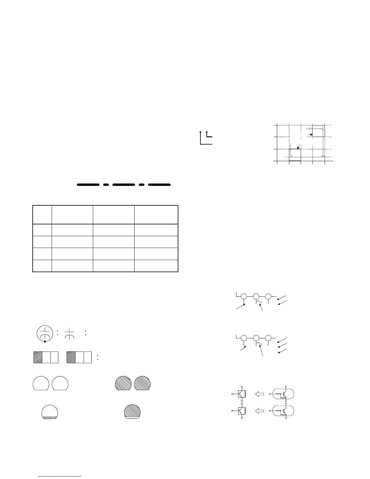
8. Voltage indications PLAY and REC modes on the
schematics are as shown below.
Mark
Capacity
change rate
Standard
temperature
Temperature
range
(B)
±10%
20°C -25~+85°C
(F) +30 - 80% 20°C –25~+85°C
(SR)
±15%
20°C –25~+85°C
(Z)
±22.5%
20°C –25~+85°C
1-D3
Distinction Area
Line Number
(1 to 3 digits)
3
2
1
ABCD
1-B1
1-D3
AREA D3
AREA B1
231
5.0
(2.5)
PLAY mode
STOP mode
5.0
The same voltage for
both PLAY & STOP modes
Indicates that the voltage
is not consistent here.
< DVD Section >
231
5.0
(2.5)
< >
PLAY mode
REC mode
DVD mode
5.0
The same voltage for
PLAY, REC & DVD
modes
Indicates that the voltage
is not consistent here.
< VCR Section >
Unit: Volts
Digital Transistor
< Schematic Diagram Symbols >
(Top View) (Bottom View)
(Bottom View)
Electrolytic Capacitor
+
Transistor or Digital Transistor
NPN Digital Transistor
PNP Digital
Transistor
(Top View)
(Top View)
E C B
E C B C B E
< PCB Symbols >
E C B
(Top View)
(Top View)
E C B
NPN Transistor PNP Transistor
C B E C B E
E C B