1-8-1 E9480DC
CABINET DISASSEMBLY INSTRUCTIONS
Comparison Chart of Models and Marks
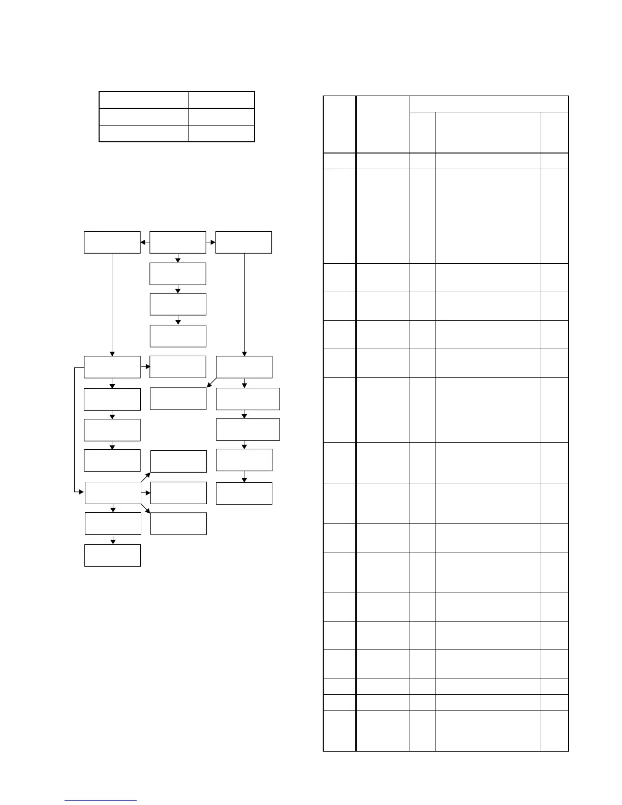
1. Disassembly Flowchart
This flowchart indicates the disassembly steps to gain
access to item(s) to be serviced. When reassembling,
follow the steps in reverse order. Bend, route, and
dress the cables as they were originally.
2. Disassembly Method
Model Mark
DVDR600VR/37 A
MRV700VR/17 B
[1] Top Cover
[2] Front
Assembly
[4] Radiation
Sheet
[3] Front
Bracket
[5] Jack-A
CBA
[6] Jack-B
CBA
[7] DVD Mecha
& FE Assembly
[8] Digital Board
Unit
[9] FFC
Friction Plate
[10] Rear
Panel Unit
[12] DC
Fan Motor
[13] PCB
Holder
[11] Power
Supply CBA
[14] Rear
Panel
[15] Front CBA
[16] Bracket R
[18] Deck
Assembly
[22] Deck
Pedestal
[19] Function
CBA
[17] VCR
Chassis Unit
[20] Main
CBA
[21] CPU
CBA Unit
[23] Front
Bracket R
ID/
LOC.
No.
PART
REMOVAL
Fig.
No.
REMOVE/*UNHOOK/
UNLOCK/RELEASE/
UNPLUG/DESOLDER
Note
[1] Top Cover D1 6(S-1) ---
[2]
Front
Assembly
D2
*2(L-1), Tray Panel,
*5(L-2), *3(L-3),
*CN204, *CN205
1
1-1
1-2
1-3
1-4
1-5
1-6
1-7
[3]
Front
Bracket
D2 2(S-2), 2(S-3) ---
[4]
Radiation
Sheet
D2 ---------- ---
[5]
Jack-A
CBA
D3 3(S-5) ---
[6]
Jack-B
CBA
D3 2(S-6) ---
[7]
DVD
Mecha &
FE
Assembly
D4
2(S-7), 2(S-8),
*CN207, *CN208,
*CN211, *CN213,
Connector 1109,
Connector 1704
---
[8]
Digital
Board
Unit
D4
4(S-9), Connector
1102
---
[9]
FFC
Friction
Plate
D5 2(S-10) ---
[10]
Rear
Panel Unit
D5
5(S-11), 3(S-12), (S-
13), *CN209, *CN210
---
[11]
Power
Supply
CBA
D6
4(S-14), AC Cord,
Earth Plate
---
[12]
DC Fan
Motor
D6 2(S-15) ---
[13]
PCB
Holder
D6 3(S-16) ---
[14]
Rear
Panel
D6 ---------- ---
[15] Front CBA D7 3(S-17), *CN214 ---
[16] Bracket R D7 2(S-18) ---
[17]
VCR
Chassis
Unit
D7
5(S-19), 5(S-20),
(S-21)
---