Safety instructions, maintenance instruction, warnings and Notes
GB 3L9.2E 2.
20- CVBS (1Vpp/75)
j
21- Earth screen
v
1.2.3 Cinch - audio/video in
V-CVBS
(yellow) (1Vpp/75))
q
L - Audio L (red) (0.2-2Vrms 10k
Ω)
q
R - Audio R
(white) (0.2-2Vrms 10k
Ω)
q
1.2.4 Headphone
- 8-600
Ω
(4mW)
t
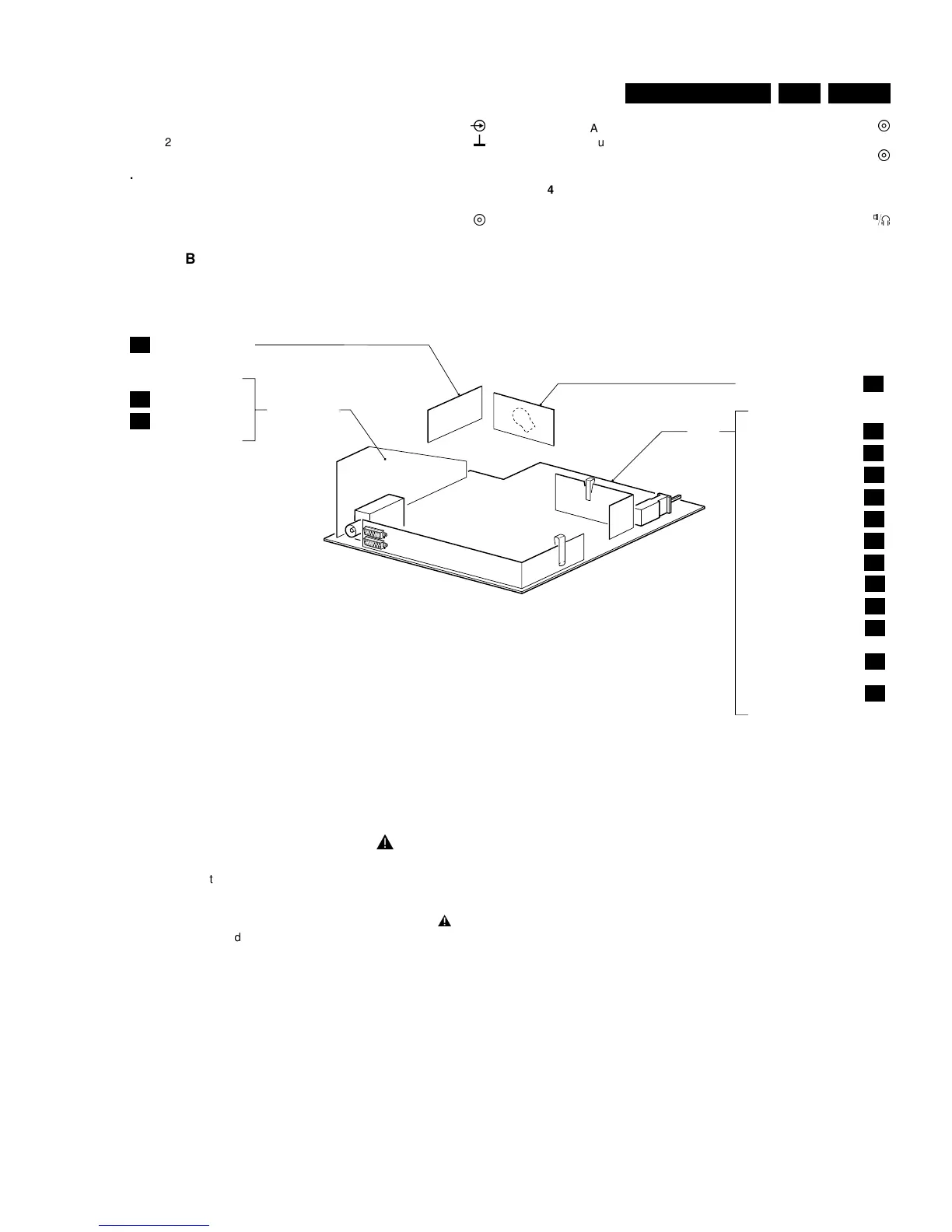
1.3 PCB location drawing
2. Safety instructions, maintenance instruction, warnings and Notes
2.1 Safety instructions for repairs
h
1. Safety regulations require that during a repair:
– The set should be connected to the mains via an
isolating transformer;
– Safety components, indicated by the symbol
h
,
should be replaced by components identical to the
original ones;
– When replacing the CRT, safety goggles must be
worn.
2. Safety regulations require that after a repair the set must
be returned in its original condition. In particular attention
should be paid to the following points.
– As a strict precaution, we advise you to resolder the
solder joints through which the horizontal deflection
current is flowing, in particular ('general repair
instruction'):
• All pins of the line output transformer (LOT);
• Fly-back capacitor(s);
• S-correction capacitor(s);
• Line output transistor;
• Pins of the connector with wires to the deflection
coil;
• Other components through which the deflection
current flows.
• Note:
• This resoldering is advised to prevent bad
connections due to metal fatigue in solder joints
and is therefore only necessary for television sets
older than 2 years.
– The wire trees and EHT cable should be routed
correctly and fixed with the mounted cable clamps.
– The insulation of the mains lead should be checked for
external damage.
– The mains lead strain relief should be checked for its
function in order to avoid touching the CRT, hot
components or heat sinks.
– The electrical DC resistance between the mains plug
and the secondary side should be checked (only for
sets which have a mains isolated power supply). This
check can be done as follows:
• Unplug the mains cord and connect a wire
between the two pins of the mains plug;
• Set the mains switch to the "on" position (keep the
mains cord unplugged!);
• Measure the resistance value between the pins of
the mains plug and the metal shielding of the tuner
A1
D1
D2
E
A2
SIDE AV PANEL
POWER SUPPLY
LINE DEFLECTION
FRAME DEFLECTION
SYNCHRONISATION
TUNER VIDEO IF
VIDEO PROCESSING
CONTROL
FRONT CONTROL
AM MONO DEMODULATOR
SMART SOUND +
MONO SOUND AMPLIFIER
FRONT CINCH +
HEADPHONE
REAR I/O SCART
A3
A4
A5
A6
A7
A8
A9
A10
A11
A13
CRT PANEL
B
AUDIO PANEL
MAIN
CL 96532028_003.eps
260399
ITT AUDIO DECODING
ITT AUDIO AMPLIFIER