Disassembly Procedures (A3)
Chapter 6 - Disassembly Guide 81
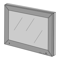
2. Use a screwdriver to remove the six fastening screws around the
periphery of the main PCB. Retain the fastening screws for reassembly.
3. Lift the main PCB slightly and unscrew the tubing connector near the
NiBP front panel fitting.
4. The main PCB can now be removed. This allows access to the SpO
2
front panel connector, NiBP fitting and backlight inverter. These can be
removed by removing the appropriate screws or nuts.
During reassembly, the backlight inverter cable should be wrapped over
the screw post. (See the upper left hand corner of the picture).
Encoder
Switch panel
connector
NiBP tubing
connector
SpO
2
cable
Backlight inverter Display backplate
Backlight
inverter
cable