7
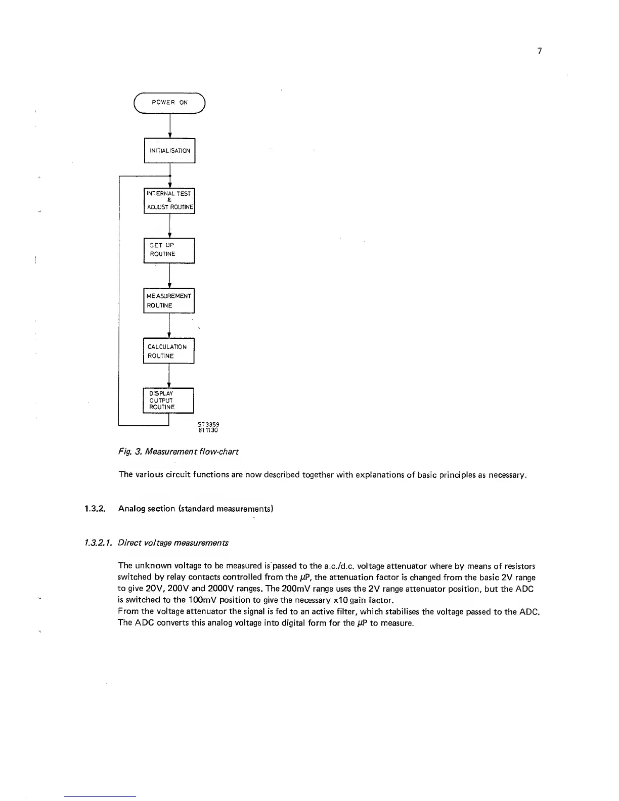
Fig.
3.
Measurement
flow-chart
The various circuit functions
are now described together
with explanations of basic principles
as
necessary.
1.3.2. Analog section (standard measurements)
1.3.2.
1.
Direct voltage measurements
The unknown voltage
to be measured
is passed to the
a.c./d.c.
voltage
attenuator where by means of resistors
switched
by
relay contacts controlled
from the
n?,
the
attenuation
factor is changed from the
basic 2V range
to give
20V, 200V
and
2000V ranges. The
200mV range uses the
2V
range attenuator
position, but the ADC
is switched to the lOOmV position
to give the necessary
xIO gain factor.
From
the voltage attenuator the signal
is
fed
to
an
active
filter, which
stabilises the voltage
passed to the
ADC.
The
ADC converts this analog voltage
into digital form for the
/iP
to
measure.