45
1.4.5. Control section
1. 4.5.1.
Interrupt con
trailer
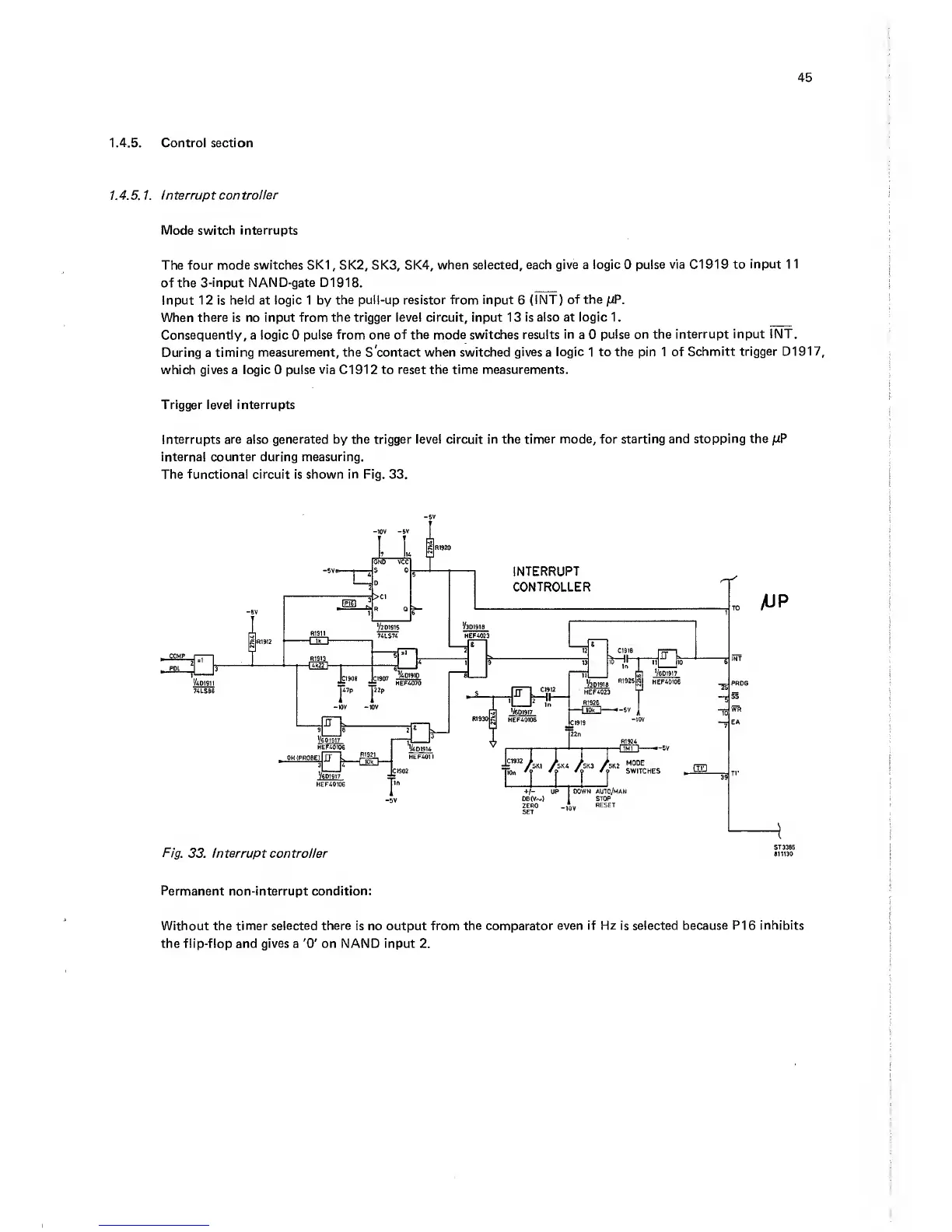
Mode switch interrupts
The four
mode switches SKI,
SK2, SK3, SK4,
when
selected, each give a logic
0
pulse via Cl 91 9 to
input 1
1
of
the 3-in
put
NAN D-gate D
1
9
1 8.
Input 12 is held at logic 1 by
the pull-up resistor from input
6
(INT)
of the ;UP.
When
there
is
no input from the trigger level circuit, input 1 3
is also at logic 1
.
Consequently, a logic
0
pulse from one of the mode switches results
in
a
0
pulse on the
interrupt input INT.
During
a timing
measurement, the S'contact when switched
gives
a
logic 1 to the pin 1
of Schmitt
trigger
D1917,
which gives a logic
0
pulse via
Cl
91
2
to reset the time measurements.
Trigger level interrupts
Interrupts are also generated by the trigger level circuit in the
timer mode, for starting and
stopping the pP
internal counter during measuring.
The
functional circuit is shown in Fig.
33.
Fig.
33.
Interrupt controller
mitao
Permanent
non-interrupt
condition;
Without the timer
selected there
is no output from
the comparator even if Hz is selected
because
PI 6
inhibits
the flip-flop and
gives
a
'0'
on NAND input 2.