21
1.
3.5.2. Interrupt controller
The interrupt controller
activates the microprocessor
interrupt input facility
to allow certain subroutines
to
be
performed either by manual
or automatic control.
The control inputs
are interrupt pulses applied from
either one of the four
front-panel mode
switches or from
timing pulses generated from the
comparator
output
in
the timing mode.
a)
Mode
switch interrupts
The
logic 0 required for interrupt
is derived from
one of the four mode
pushbuttons.
It
provides
for: UP and
DOWN ranging in the manual
mode,
AUTO ranging (except
in timer function).
—
Trigger mode
polarity selection
—
Selecting relative
reference
with ZERO SET in
Vtt., dB,
12,
and
°C
range
—
Manual STOP/RESET
in timing
mode
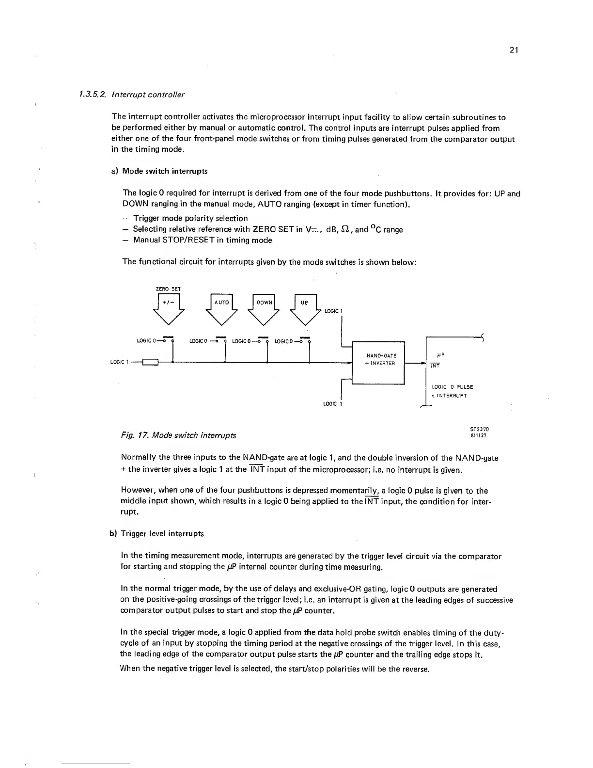
The functional circuit for
interrupts
given by the mode
switches is shown below:
ZERO SET
Normally the three inputs
to
the
NAND-gate
are at logic
1,
and the double
inversion of the
NAND-gate
-I-
the inverter gives
a logic 1
at
the
INT input of the microprocessor;
i.e. no
interrupt
is given.
However,
when one of the four
pushbuttons
is depressed momentarily,
a logic
0
pulse
is given to the
middle
input shown, which results
in a logic
0 being applied
to
the
INT input, the condition for
inter-
rupt.
b) Trigger level interrupts
In the
timing
measurement
mode,
interrupts
are generated by the trigger
level circuit via the
comparator
for starting and
stopping the pP internal
counter during
time measuring.
In the normal
trigger mode, by the use of
delays and exclusive-OR
gating, logic
0 outputs are generated
on the positive-going crossings
of the
trigger level; i.e. an interrupt
is given
at the
leading
edges of successive
comparator output pulses
to start and
stop the juP counter.
In the
special trigger mode, a logic
0 applied from the
data hold probe
switch enables timing of
the duty-
cycle of an input
by stopping the
timing period
at
the negative
crossings of the
trigger level. In this
case,
the leading
edge of the comparator
output
pulse starts the juP
counter and the trailing edge
stops it.
When the negative trigger
level is selected,
the start/stop
polarities will be the
reverse.