19
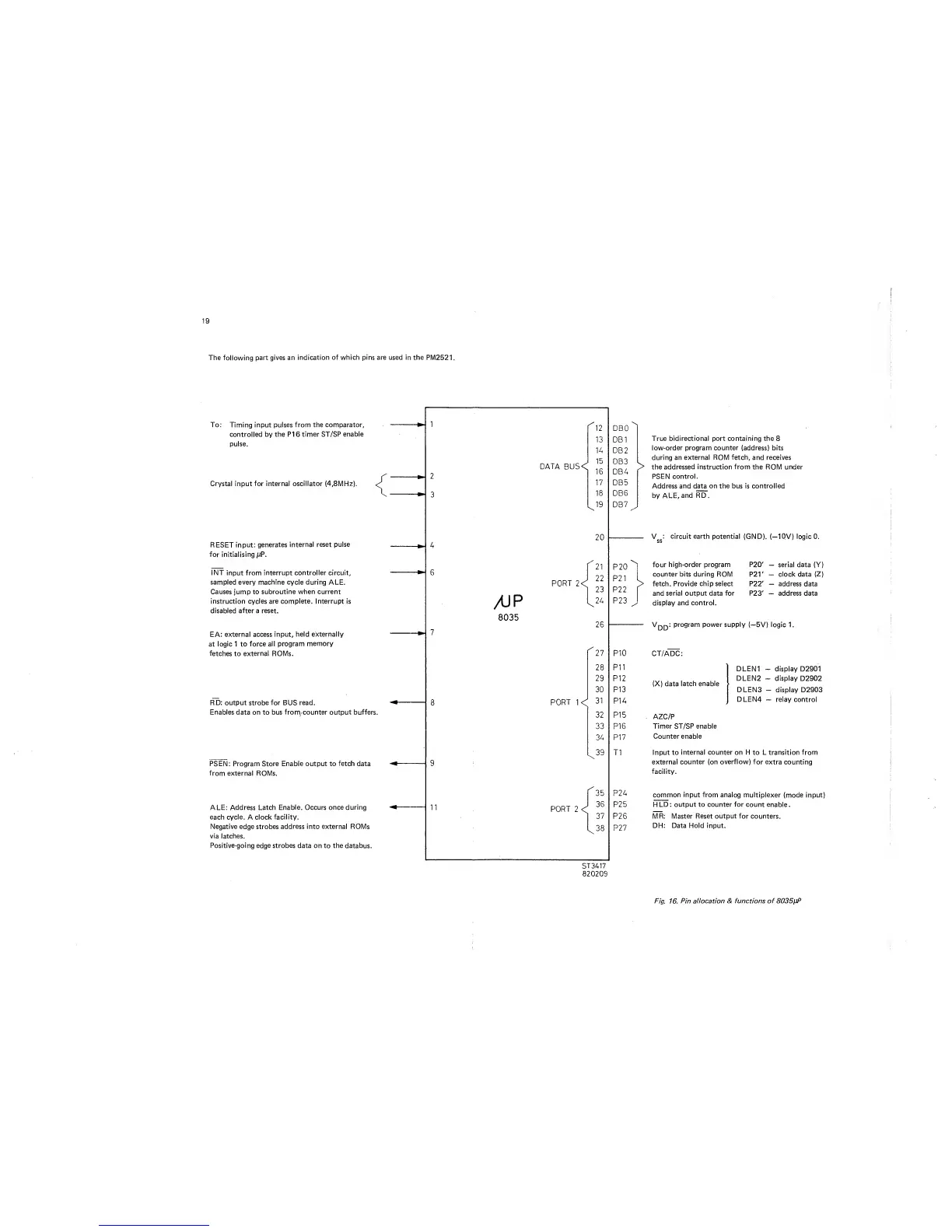
The following
part gives an
indication of which pins are used in the
PM2521.
To:
Timing input
pulses from the comparator,
controlled by the PI
6
timer ST/SP enable
pulse.
Crystal
input
for internal oscillator (4,8MHz).
RESET input:
generates
internal reset pulse
for initialising jjP.
INT
input from
interrupt controller
circuit,
sampled every machine cycle during ALE.
Causes jump
to
subroutine when current
instruction cycles are complete. Interrupt
is
disabled after
a
reset.
EA: external
access input, held externally
at
logic
1 to
force all
program
memory
fetches
to
external ROMs.
RD: output strobe for BUS read.
Enables data on to bus frorn, counter output buffers.
PSEN: Program Store
Enable output
to
fetch
data
from external ROMs.
ALE: Address Latch
Enable. Occurs once during
each cycle.
A clock
facility.
Negative edge strobes
address
into
external
ROMs
via latches.
Positive-going
edge
strobes
data on to the databus.