23
I
b)
Control outputs
i
The microcomputer
controls
the
analog section, in
accordance with the input information received,
by
I
means
of reed relays and FET
switches.
The output
data is clocked into a
relay
control unit which supplies
function and range
information
to the analog
section for switching purposes. Additional
outputs are
set/reset
commands for the
timing
measurements,
trigger level, dB conversion, and ZERO
SET command
i
for the relative reference value.
/. 3. 5.
5.
ROM's
and address/da
ta
decoding
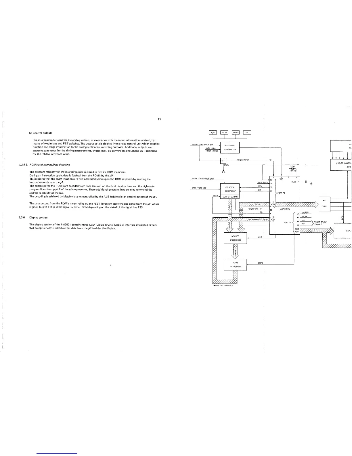
The program memory for the
microprocessor
is
stored in
two 2k ROM memories.
During
an instruction cycle, data
is fetched from
the ROM's
by
the /tP.
This
requires that the
ROM locations
are first
addressed
whereupon the
ROM
responds
by sending the
instruction or data to the
/xP.
The addresses for the ROM's are
decoded
from data
sent out on the
8-bit databus lines and
the high-order
program lines from port
2
of the
microprocessor.
These
additional program lines are
used to extend
the
address capability of the bus.
The decoding is achieved
by bistable
latches
controlled
by
the
ALE (address latch enable)
output
of the /xP.
The data output from the
ROM's is
controlled
by
the
PSEN (program store enable)
signal from
the /xP, which
is gated
to
give
a
chip select
signal
to either
ROM depending
on the stated of the
signal line P23.
1.3.6.
Display
section
\
The display section of the PM2521
contains three
LCD (Liquid Crystal Display)
interface integrated
circuits
‘
that accept serially clocked
output data
from the ^xP
to drive the
display.
I
/