23
24
ance
with the input information
received,
by
s clocked
into a relay control unit
which supplies
iwitching
purposes. Additional outputs are
evel,
dB
conversion,
and ZERO SET
command
)
2k
ROM memories,
by the
/jP.
reupon
the
ROM responds by sending the
on the
8-bit databus
lines and
the high-order
tional
program lines are used to extend the
e ALE
(address latch enable)
output
of the
/tP.
(program
store enable)
signal from the /iP, which
on the
stated of the
signal line P23.
jid
Crystal Display) interface integrated
circuits
the display.
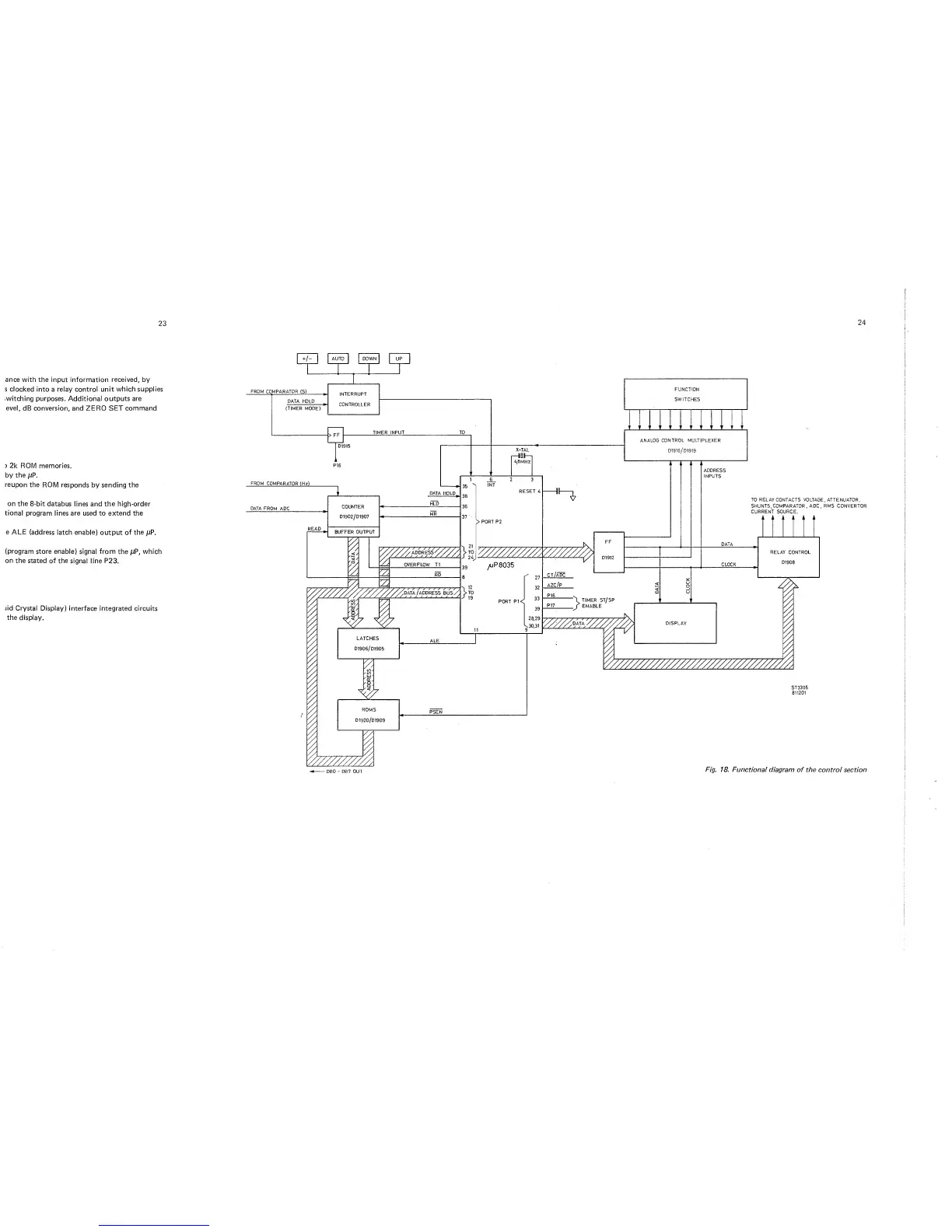
Fig. 18. Functional
diagram of the
control
section