26
1.4. DETAILED
CIRCUIT
DESCRIPTION
1.4.1. Measuring
sequence
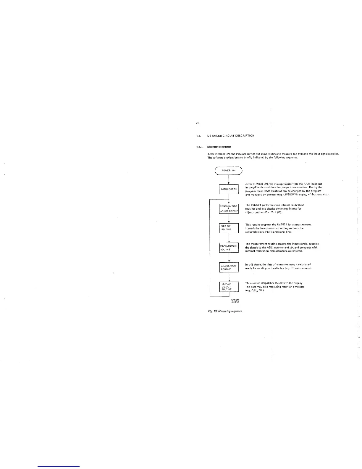
After
POWER ON, the PM2521
carries out some
routines
to
measure
and
evaluate
the input signals applied.
The
software applications
are briefly indicated
by
the following
sequence.
/
After
POWER ON,
the
microprocessor fills the
RAM
locations
in the
jJP with conditions for jumps to
subroutines.
During the
program
these
RAM locations can be changed by
the program
and manually
by the user (e.g.
UP/DOWN ranging,
+/-
buttons, etc.).
The PM2521
performs some internal
calibration
routines and also
checks the analog inputs for
adjust routines
(Port 2 of
/tP).
This routine
prepares
the
PM2521
for
a
measurement.
It
reads the
function switch setting
and sets the
required relays,
FET's and
signal
lines.
The
measurement routine accepts the input signals, supplies
the
signals
to
the ADC, counter and juP, and compares
with
internal calibration measurements, as required.
In this phase,
the data of a measurement is
calculated
ready for sending to
the display
(e.g.
dB calculations).
This routine despatches
the
data to the display.
The
data
may be a measuring result or a message
(e.g. CAL;
OL).
5T3359
81
1130
Fig.
19.
Measuring
sequence