130
OQ0063
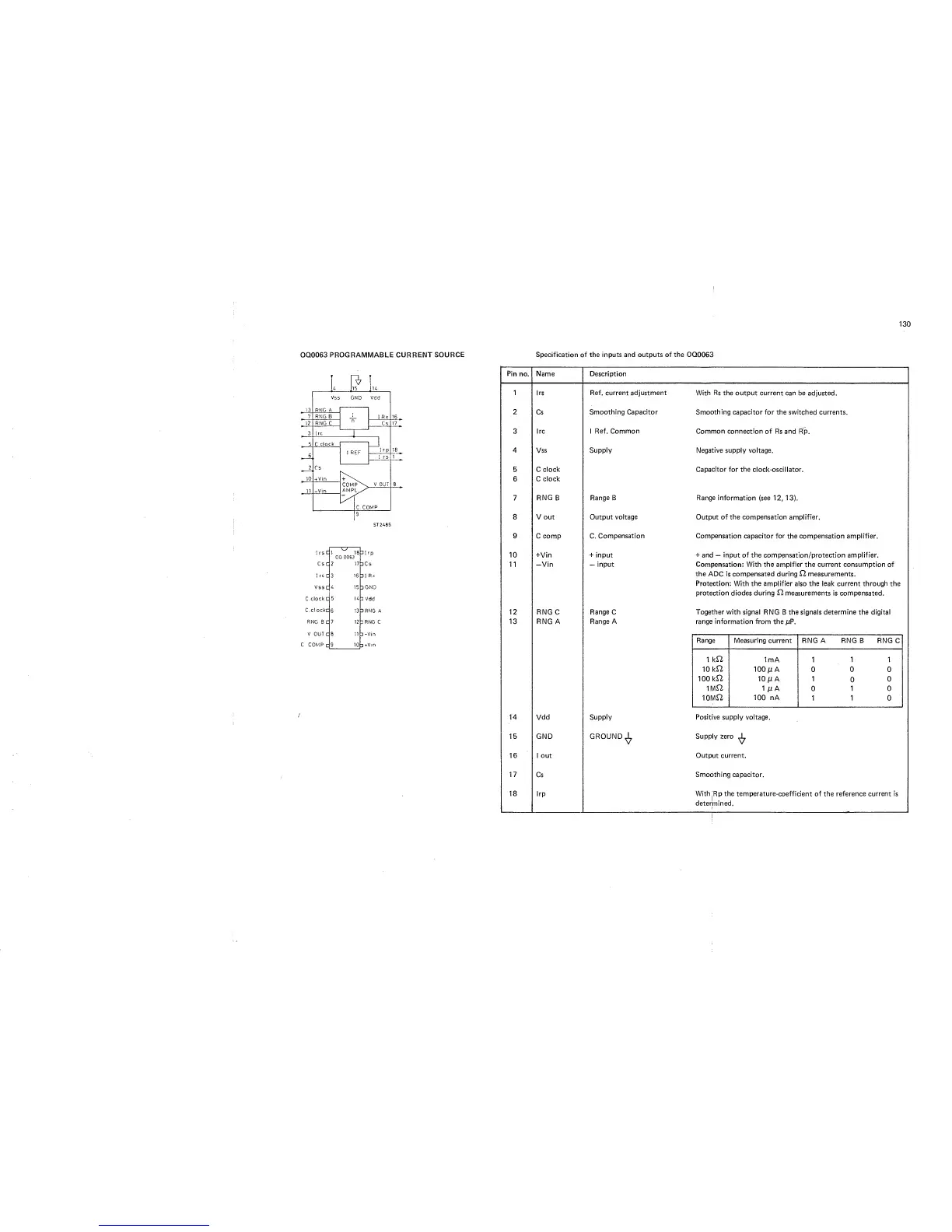
PROGRAMMABLE CURRENT SOURCE
Specification of the inputs and outputs of
the
OQ0063
ST2485
IrsC
Csc
1
rc
c
Vssc
C,
clock
C
C.cl ockc
RNG
B
C
V
OUT
c
C COMP,
c
Olrp
Cs
01
Rx
OGND
1 Vdd
3
RNG A
3
RNG
C
-Vin
+Vin
Pin
no.
1
2
3
4
5
6
7
8
9
10
11
12
13
14
15
16
17
18
Name
Description
Irs Ref. current adjustment
Cs
Smoothing Capacitor
Ire 1
Ref. Common
Vss Supply
C
clock
C clock
RNG B
Range
B
V out Output
voltage
C comp C.
Compensation
-HVin
-1-
input
—Vin
—
input
RNG C
Range
C
RNG A
Range
A
Vdd Supply
GND GROUND^
1 out
Cs
irp
With
Rs
the output current can be adjusted.
Smoothing capacitor for
the switched currents.
Common connection of
Rs
and
Rp.
Negative supply voltage.
Capacitor for the
clock-oscillator.
Range
information (see
12,
13).
Output of the compensation amplifier.
Compensation
capacitor for the compensation amplifier.
+
and
—
input of the compensation/protection amplifier.
Compensation: With the ampifier the
current
consumption of
the ADC
is
compensated
during
measurements.
Protection: With the amplifier
also the
leak
current
through
the
protection diodes during 12 measurements
is
compensated.
Together with signal
RNG B the signals
determine
the digital
range
information from the
[jP.
Range Measuring current
RNG A RNG B RNG
C
1
kl2
1mA
1
1 1
10kl2
100
A
0
0
0
100
kl2
10m
A 1
0
0
1Ml2
1
ma
0
1 0
10M12
100
nA
1 1 0
Positive
supply voltage.
Supply zero
^
Output current.
Smoothing capacitor.
With
Rp
the temperature-coefficient
of the
reference current is
determined.