2
1.
CIRCUIT
DESCRIPTION
1.1.
GENERAL
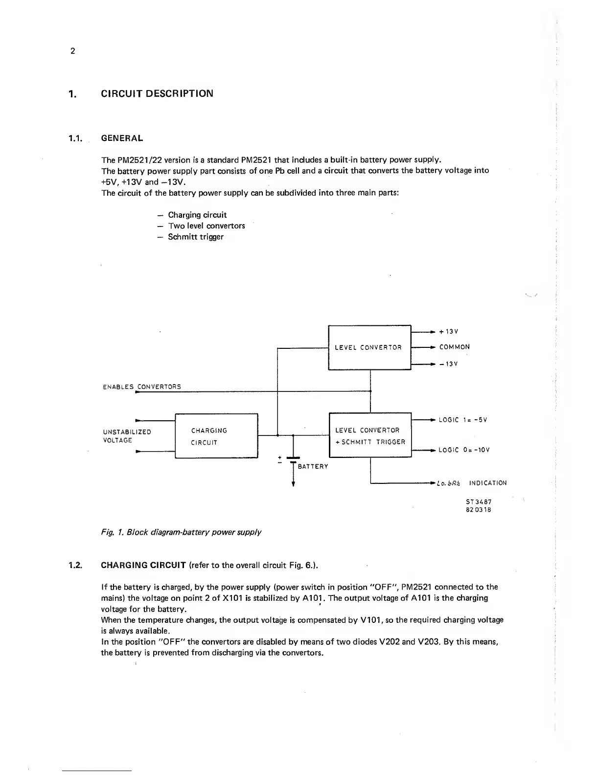
The PM2521/22
version is a standard PM2521 that
includes a built-in
battery power
supply.
The battery power supply
part consists of one Pb
cell and a circuit
that converts the
battery voltage into
-I-5V,
-M3Vand-13V.
The circuit of the
battery power supply can be subdivided into
three main parts:
—
Charging circuit
—
Two level convertors
—
Schmitt
trigger
+
13V
COMMON
-13V
LOGIC 1
=
-5V
LOGIC
0=
-10V
Lo.bRk
INDICATION
5T3487
82 0318
Fig.
1. Block
diagram-battery
power supply
1.2. CHARGING CIRCUIT
(refer
to the overall circuit Fig.
6.).
If the battery is charged, by the power
supply
(power switch in position "OFF", PM2521
connected
to
the
mains)
the
voltage on
point
2
of
X101 is
stabilized
by A101. The output
voltage of
A101
is the
charging
voltage
for the battery.
When the temperature changes, the
output voltage is
compensated
by V101, so
the required charging
voltage
is always available.
In the position "OFF"
the
convertors are disabled by means of two diodes V202 and V203. By
this means,
the battery is prevented
from discharging
via the convertors.