14
1.3.4. Analog
section (multifunction circuits)
1.
3.4.1.
R.M.S. convertor
Basically, the
circuit
is
an
a.c. to d.c.
convertor built around the
OQ0061 1C,
which consists of three parts:
—
A
voltage-to-current convertor with two
selectable
input
ranges
—
A current
rectifier with offset cancellation
—
A log-antilog calculating R.M.S circuit
Circuit element
principles:
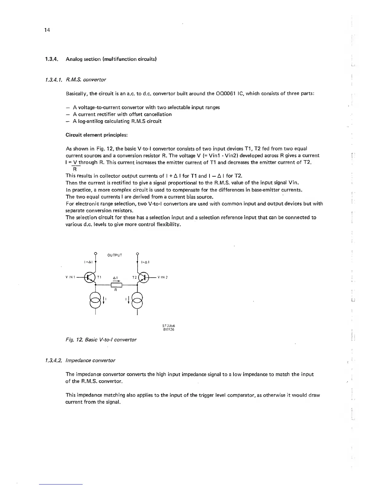
As shown in Fig.
12,
the
basic
V-to-l convertor consists of two input
devices T1,
T2
fed from two
equal
current sources and a conversion resistor
R.
The
voltage V
(=
Vini
-
Vin2) developed across R
gives a current
I
=
V
through
R. This current increases the emitter
current
of
T1
and decreases the emitter
current of T2.
This
results
in collector output currents of
I
-t
A
I for
T1
and I
—
A I
for
T2.
Then the current is
rectified
to
give
a signal proportional to
the R.M.S.
value of the input
signal Vin.
In practice, a
more complex
circuit is used to compensate for the
differences in base-emitter currents.
The two equal currents I are derived from a current
bias
source.
For electronic
range selection, two
V-to-l
convertors
are used with
common input and output devices but with
separate conversion resistors.
The
selection circuit
for these has
a
selection
input and a selection
reference
input that can be
connected
to
various d.c.
levels
to
give more
control flexibility.
ST3Jb6
811126
Fig.
12. Basic V-to-i
convertor
1. 3.4.2. impedance convertor
The impedance convertor converts the high input
impedance signal to a low
impedance
to
match the input
of the R.M.S.
convertor.
This impedance matching also
applies to the input of the trigger level comparator,
as
otherwise it would draw
current
from
the signal.