33
1.4.2. Analog
section
1. 4.2.1.
Direct voltage
measurements (V~.)
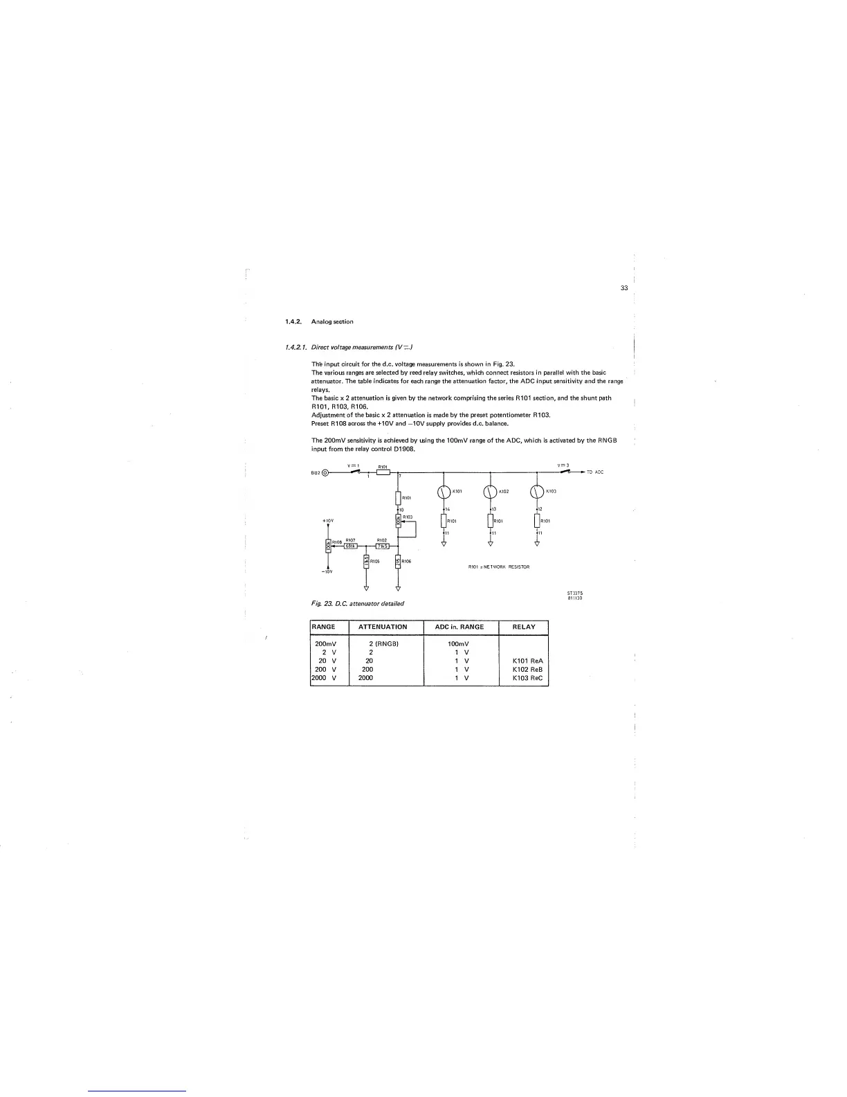
Th'e input circuit for
the
d.c. voltage measurements is shown
in
Fig. 23.
The various
ranges are selected
by
reed
relay
switches, which connect resistors in parallel with the basic
attenuator.
The table indicates for each range the attenuation factor, the ADC input sensitivity and the range
relays.
The basic x 2
attenuation is given by
the
network comprising the series
R101
section, and the shunt path
R101,
R103,
R106.
Adjustment of the basic x 2 attenuation
is
made by the preset potentiometer R103.
Preset R108 across
the
+10V and
—10V
supply provides d.c. balance.
The 200mV sensitivity is achieved by using the lOOmV range of the ADC, which is activated by
the
RNGB
input from the relay control
D1908.
V
—
1
R,01
''
-
3
RANGE ATTENUATION
ADC in. RANGE RELAY
200mV
2
(RNGB) lOOmV
^ V \
V
20
V
20
1 V K101 ReA
200
V
200
1
V
K102
ReB
2000
V
2000
1 V K103 ReC