Technical Data
7.3 Connector Pinouts
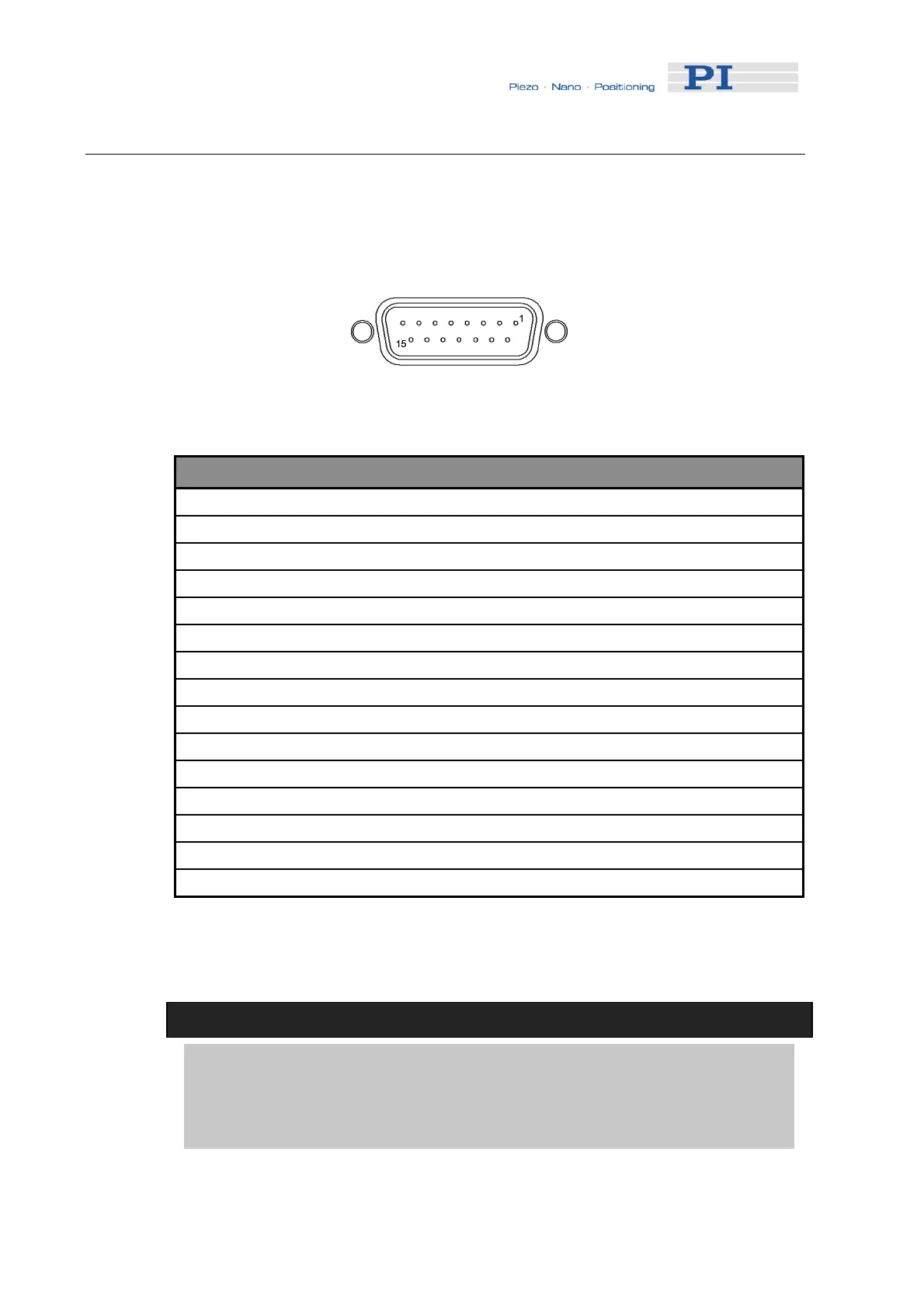
7.3.1 Motor-Connector
Fig. 14: Sub-D 15(f) motor connector
Pin Pin Function
1 Programmable output (brake control) (0 or + 5V)
9 Motor – (differential, power PWM*)
2 Motor + (differential, power PWM*)
10 Power GND
3 PWM magnitude (TTL-level output)
11 PWM sign (motion direction, TTL-level output)
4 +5 V (output)
12 Negative limit signal (input)
5 Positive limit signal (input)
13 Reference signal (input)
6 Limit GND
14 Encoder: A(+) / ENCA (input)
7 Encoder: A( - ) (input)
15 Encoder: B (+) / ENCB (input)
8 Encoder: B ( - ) (input)
* PWM (pulse-width modulation) ON-voltage magnitude on these lines is close to
the supply voltage.
!
CAUTION
The voltage output on the “Motor +” and “Motor -“ pins can be as high as the
supply voltage used. If using a non-standard power supply for the Mercury™
and a motor that connects to these lines (i.e. without separate PWM
amplifier), make sure the motor’s operating voltage will not be exceeded.
www.pi.ws C-863 MS173E Release 1.2.7 Page 35
 Loading...