Quick Start
2.4 Starting Operation
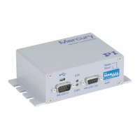
1 Make sure each controller is set to a suitable device address. The factory
default setting of the address DIP switches is all ON, corresponding to
device number 1. Each Mercury™ Class controller in a network must be
set to a unique address. See ”DIP Switch Settings,” p. 23 for details on
setting device numbers.
2 If there are to be additional controllers in the network, chain them from
RS-232 Out to the RS-232 In of successive units.
Use C-862.CN straight-through RS-232 cables (M-F) between the units.
Between the first controller and the PC use either the USB cable or the
null-modem RS-232 cable, but not both. Each controller on the network
must be set to the same baud rate (DIP switches 5 and 6 on the C-863)
and it must be the same as that assumed by the host software.
!
CAUTION
Never connect a stepper motor drive to a C-863 DC motor controller.
Irreparable damage could result.
!
CAUTION
The voltage output on the “Motor +” and “Motor -“ pins can be as high as the
supply voltage used. If using a non-standard power supply for the Mercury™
and a motor that connects to these lines (i.e. without separate PWM
amplifier), make sure the motor’s operating voltage will not be exceeded.
3 Connect each motorized axis to the corresponding controller.
CAUTION
!
Always respect the power supply voltage markings. Never connect a 24 V
power supply to an old (black) C-862 Mercury™
4 Connect a protective ground to the grounding screw on the rear panel
5 Connect power to each of the controllers. If there are C-862 (black)
Mercurys™ in the system, be especially careful when connecting the
power supplies.
6 The status LED (label STA) will glow green for normal operation.
www.pi.ws C-863 MS173E Release 1.2.7 Page 15
 Loading...