Technical Data
RS-232 IN and RS-232 OUT Connectors
Pin on all
Mercury™
Connectors
Signal name on all
Mercury™
Connectors*
Signal direction Function
1 n.c.
2 RxD* PC to controller** Commands
3 TxD* Controller** to PC Reports (responses)
4 n.c.
5 GND GND
6 n.c.
7 n.c.
8 n.c.
9 n.c.
*The RS-232 connection with the PC is via null-modem cable, so the connected signal names on the PC side are
reversed.
** If the PC connection is via USB, then the Mercury™ connected to the PC copies everything received from the
host over USB to the Mercury™ RxD line of both its RS-232 connectors. It also copies everything it sees on the
Mercury™ TxD line to the host via USB.
CAUTION
Never connect the RS-232-IN and USB connectors of the same controller to a
PC at the same time, as damage may result.
www.pi.ws C-863 MS173E Release 1.2.7 Page 38
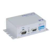
Fig. 18: Mini type-B USB connector (top) and sub-D 9-pin RS-232 (bottom)
7.3.6 USB Connector
Industry-standard mini type-B USB connector.
 Loading...