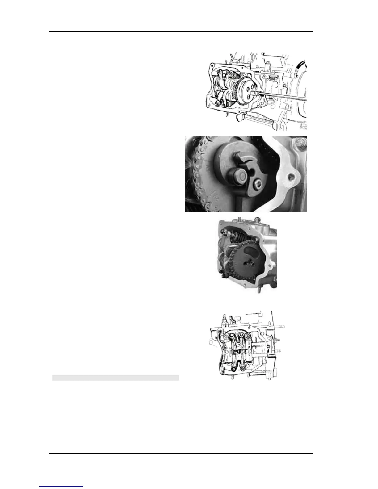
- Refit the spacer on the cam shaft.
- Rotate the engine so that the piston is at top dead
centre, using the reference marks on the flywheel
and the crankcase.
- Holding this position insert the chain on the cam-
shaft control pulley.
- Insert the pulley on the cam shaft while keeping
the reference 4V in correspondence with the ref-
erence mark on the head.
- Fit the counterweight and tighten the fixing screw
to the prescribed torque.
-Fit the end-stop ring on the automatic valve-lifter
cam and fit the automatic valve-lifter cam to the
cam shaft.
- Fit the automatic valve-lifter return spring.
- During this operation the spring must be loaded
by approximately 180°.
- Fit the automatic valve-lifter retaining dish, using
the counterweight screw fastener as a reference.
- Tighten the clamping screw to the prescribed tor-
que.
- Set the tensioner cursor in the rest position.
- Fit the chain tensioner on the cylinder, using a
new gasket, and tight the two screws to the pre-
scribed torque.
- Insert the chain tensioning screw, together with
the spring and washer, tightening it to the prescri-
bed torque.
- Adjust the valve clearance.
- Fit the spark plug.
Electrode distance 0.8 mm
N.B.
GREASE THE END STOP RING TO PREVENT IT COMING
OUT AND FALLING INTO THE ENGINE.
Locking torques (N*m)
Timing chain tensioner support screw 11 ÷ 13
Spark plug 12 ÷ 14 Starter ground screw 7 ÷ 8.5
Timing chain tensioner slider screw 10 ÷ 14
Starter ground support screw 11 ÷ 15 Timing
chain tensioner central screw 5 - 6 Camshaft re-
tention plate screw 4 ÷ 6
Engine Carnaby 125 - 200
ENG - 152