OPERATING AND INSTALLATION MANUAL HEAT PUMP COMBI UNIT PKOM4 PAGE 24
USER
GENERALSPECIALIST PERSONNEL
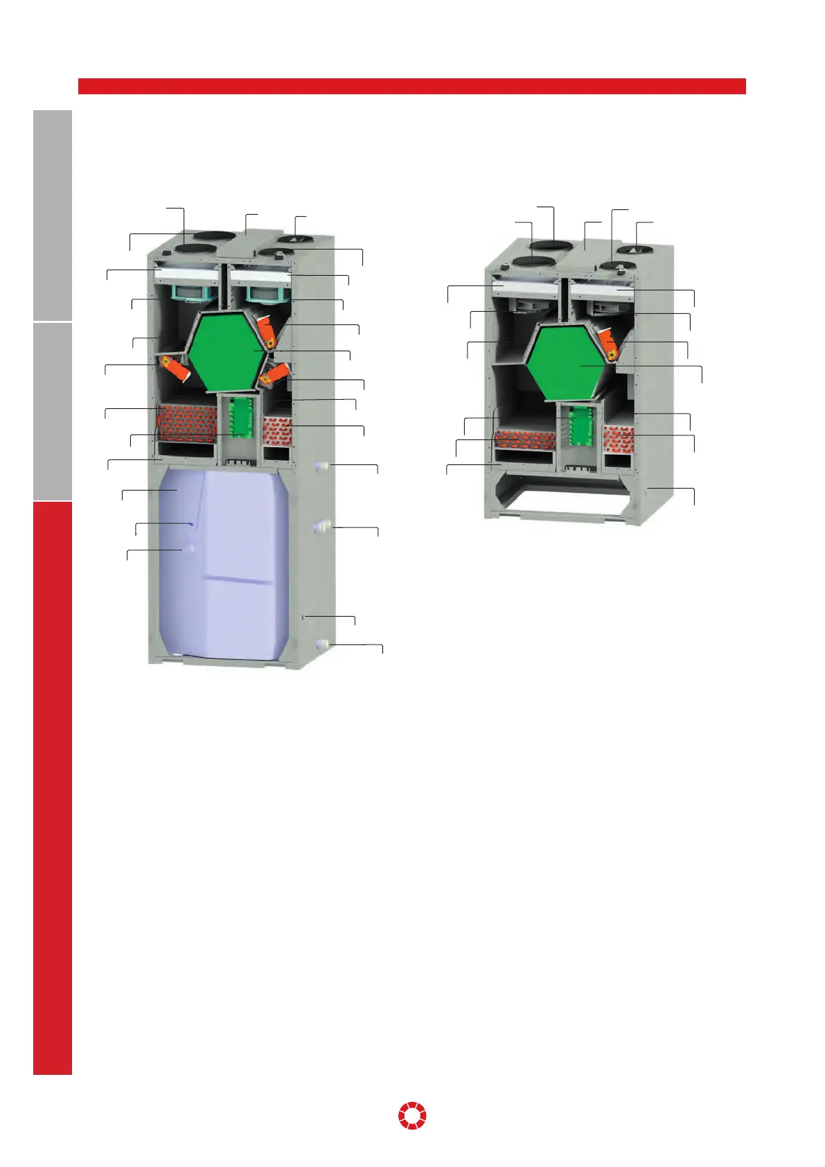
11. Layout sketch
11.1 PKOM
4
CLASSIC (RIGHT-HANDED VERSION) 11.2 PKOM
4
TREND (RIGHT-HANDED VERSION)
1 Supply air (SUP)
2 Extract air (ETA)
3 Outdoor air (ODA)
4 Exhaust air (EHA)
5 Filter ODA ISO ePM1 55%
6 Filter ETA ISO ePM10 75%
7 Outdoor air fan
8 Extract air fan
9 Bypass flap with servo motor
10 Pre-heater battery for outdoor air
11 Counterflow heat exchanger
12 ODA/EHA flap with servo motor
13 ODA/SUP flap with servo motor
14 Compressor in housing
15 Heat exchanger in exhaust air
16 Heat exchanger in supply air
17 Condensate tray
18 Household hot water tank
19 Sacrificial anode
20 Electrical heating element with thermal cut-out
21 Hot water connection 1“AG
22 Heat exchanger connection 1“AG
23 Cold water connection 1“AG
24 Condensate drain
25 Electrical connection box with main PCB
26 Heat pump PCB
5
7
10
15
26
6
16
24
8
9
14
11
3
4
2
1
25
6
8
9
11
13
14
16
21
22
24
23
20
19
18
17
17
26
15
12
10
7
5
3
4
25
2
1