OPERATING AND INSTALLATION MANUAL HEAT PUMP COMBI UNIT PKOM4 PAGE 28
USER
GENERALSPECIALIST PERSONNEL
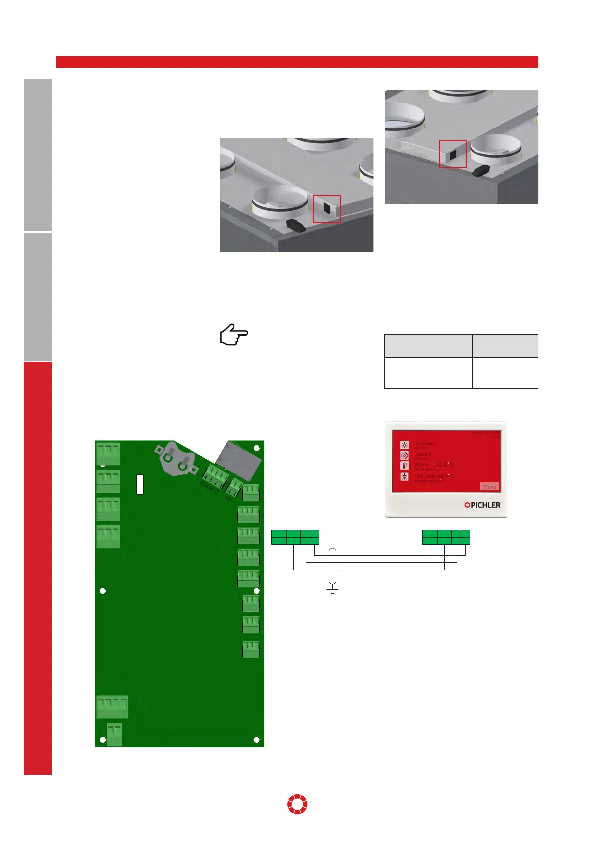
13.3 DEVICE SWITCH The device switch is located at the top of
the unit, at the side of the electrical connec-
tion box (see Section 11, page 24, position
25).
Illustration: Device switch right version
Illustration: Device switch left version
To always have the control and potential
messages in view, the control unit should
be installed centrally in the dwelling.
The temperature sensor is locat-
ed on the underside of the control
unit. To ensure accurate and conclusive
temperature measurement, it is important
to place the control unit in a location that:
•
is not exposed to direct sunlight.
•
is not located directly above or close to a
source of heat (e.g. room heater).
Dimensions
(W x H x D)
110 x 84 x 25 mm
Cable Telephone installa-
tion cable (max. Installa-
tion length < 100m)
J-Y(ST)Y 2x2x0.8
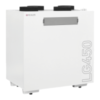
13.4 ELECTRICAL WIRING DIAGRAM
TOUCH CONTROL UNIT
F3
F4
F6 F1
F5
F2
T2AH230V
T10AH230V
T2AH230V
T8AH230V
T500mAH230V
T500mAH230V
M3
M2
M1
M4
S2
S1
E1/T40
H2
H3
H1
K6
K5
K4
3 2 1
3 2 1
3 2 1
3 2 1
4 3 2 1
2 1
T9
3 2 1
3 2 1
3 2 1
3 2 1
4 3 2 1
4 3 2 1
4 3 2 1
4 3 2 1
M4
24V GND
34
- +
12
Display
24V GND
34
- +
12
Schirm mit PE verbinden!
Connect shielding to ground!
08PKOM4ES1086
Tuesday, 26.05.2018
13:45
Summer
Automatic
Level 2
Scheduler
Room 22.0 °C
Normal mode 22 °C
Menu
Hot water 49.0 °C
Normal mode 50 °C