OPERATING AND INSTALLATION MANUAL HEAT PUMP COMBI UNIT PKOM4 PAGE 37
USER
GENERALSPECIALIST PERSONNEL
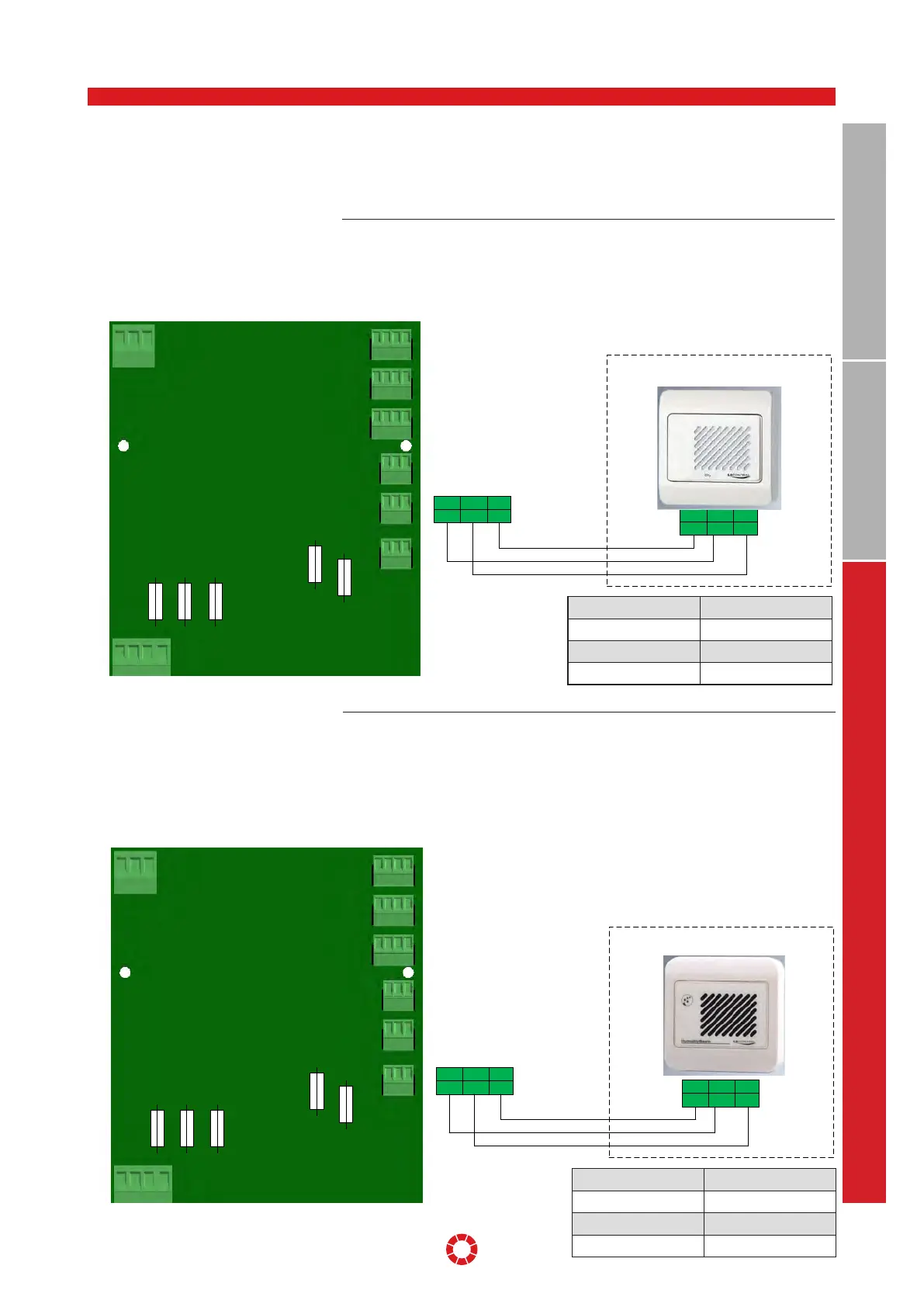
Illustration: Electrical connection of main board
14.6 DEMAND-DRIVEN CONTROL OF
THE AIR VOLUMES
The air volume flow can be either defined
manually or controlled via a scheduler –
see Section 8, item 8.1.4, page 15 .
Up to two dierent additional sensors may
be optionally installed for demand-driven
control.
14.6.1 CO
2
sensor Air volume flows are generally specified
via the values selected in the scheduler or
via manually selected values. If a CO
2
sen-
sor is configured via the data logger, the
air volumes are increased automatically as
soon as the preset CO
2
threshold value is
exceeded (default setting 1000 ppm).
F3
F4
F6 F1
F5
T10AH230V
T2AH230V
T8AH230V
T500mAH230V
T500mAH230V
M3
M2
M1
M4
S2
S1
H3
H1
3 2 1
3 2 1
3 2 1
3 2 1
4 3 2 1
2 1
T9
3 2 1
3 2 1
3 2 1
4 3 2 1
4 3 2 1
4 3 2 1
07RCO248330
GND
3
0-10V 24V
12
S2
24V
4
GND 0-10V
65
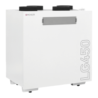
Colour white
Measuring range 0-100 % RH
Guide signal 0-10 V
Dimensions W x H x D 85 x 85 x 35 mm
14.6.2 Humidity sensor Air volume flows are generally specified
via the values selected in the scheduler or
via manually selected values. If a humid-
ity sensor is configured via the data logger,
the air volumes are automatically increased
when the preset maximum relative humid-
ity is exceeded, and they are automatically
reduced if the value falls below the preset
minimum relative humidity. (Default setting
min. 30 %, max. 60 %).
Illustration: Electrical connection of main board
F3
F4
F6 F1
F5
T10AH230V
T2AH230V
T8AH230V
T500mAH230V
T500mAH230V
M3
M2
M1
M4
S2
S1
H3
H1
3 2 1
3 2 1
3 2 1
3 2 1
4 3 2 1
2 1
T9
3 2 1
3 2 1
3 2 1
4 3 2 1
4 3 2 1
4 3 2 1
07RHF49360
GND
3
0-10V 24V
12
S1
24V
4
GND 0-10V
65
Colour white
Measuring range 0-2000 ppm
Guide signal 0-10 V
Dimensions W x H x D 85 x 85 x 35 mm