OPERATING AND INSTALLATION MANUAL HEAT PUMP COMBI UNIT PKOM4 PAGE 35
USER
GENERALSPECIALIST PERSONNEL
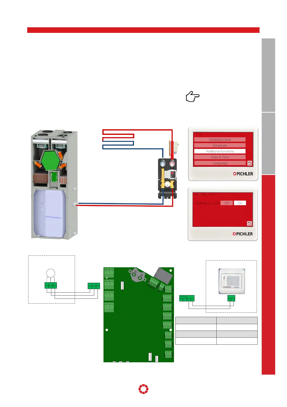
The heating circuit module allows for the
connection of a small, water-controlled
heating circuit (e.g. underfloor heating in
the bathroom, towel dryer, etc.) up to a max.
heat consumption of 500 watts. The mod-
ule is connected to the heating battery of
the service water tank. The room tempera-
ture sensor records the room temperature
in the area in which the heating circuit is
installed. For this room, an individual tem-
perature setpoint can be specified on the
control unit.
As an alternative, instead of the heating
circuit, an electrical additional heating (IR
panel, electric underfloor heating. electric
radiator, etc.) can also be activated via this
function by means of an external relay.
In the [settings] > [additional functions] the
heating circuit must be activated.
Observe the maximum electrical
load. Electric radiators must be
supplied and fused separately.
14.4 HEATING CIRCUIT
Illustration: Assembly situation
Illustration: Configuration of operating unit
F3
F4
F6 F1
F5
F2
T2AH230V
T10AH230V
T2AH230V
T8AH230V
T500mA
H230V
H230V
M3
M2
M1
M4
S2
S1
E1/T40
H1
K6
K5
K4
3 2 1
3 2 1
3 2 1
3 2 1
T9
3 2 1
3 2 1
3 2 1
3 2 1
4 3 2 1
4 3 2 1
4 3 2 1
4 3 2 1
4 3
E1
2 1
T40
NTC
3
1
K5(230V)
PE
N L
2
5 4
07RTF49357
NTC
3
1
PE
N L
2
M
Pumpe
Pump
08PKOM4HBK33
08PKOM4WHHBK
Illustration: Electrical connection of main board
Colour white
Type NTC 10 kOhm
Guide signal 0-10 V
Dimensions W x H x D 85 x 85 x 35 mm
Settings
Scheduler
Ventilation level
Additional functions
Date & Time
Language
On
Off
Heating circ. (AF)
Settings additional function