OPERATING AND INSTALLATION MANUAL HEAT PUMP COMBI UNIT PKOM4 PAGE 32
USER
GENERALSPECIALIST PERSONNEL
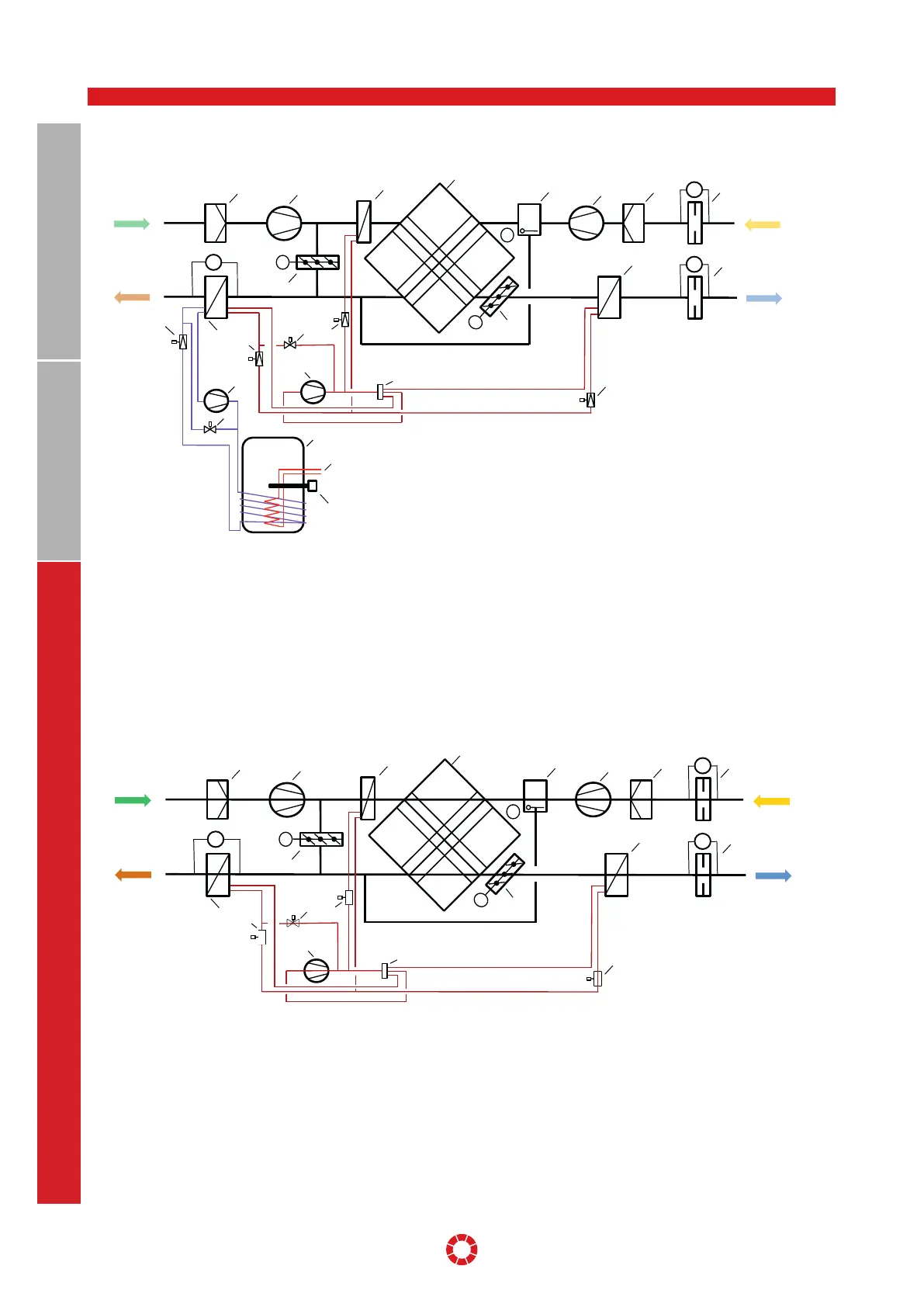
EN FUNCTIONAL DIAGRAM PKOM4 CLASSIC
dp
dp
M
M
M
dp
air / ODA
air / EHA
Heat pump circuit
domestic hot water (DHW)
Heat pump circuit, ventilation
(HC heating cooling)
1
2
3
7
6
5 4
13
12
11
9
22
15
19
Supply air
Extract air
10
14
20
18
16
25
23
24
21
17
EN FUNCTIONAL DIAGRAM PKOM4 TREND
14.1.1 Functional diagram PKOM
4
classic
14.1.2 Functional diagram PKOM
4
trend
EN FUNCTIONAL DIAGRAM PKOM4 CLASSIC
1
2
3
7
6
5
dp
4
Outdoor air / ODA
Extract air / ETA
M
dp
M
12
dp
13
Exhaust air / EHA
9
Supply air / SUP
M
17
11
10
16
18
14
15
19
Heat pump circuit, ventilation
(HC heating cooling)
EN FUNCTIONAL DIAGRAM PKOM4 TREND
1 Filter ODA ISO ePM1 55%
2 Outdoor air fan
3 Pre-heater battery for outdoor air (WT1)
4 Air volume measurement, extract air
5 Filter ETA ISO ePM10 75%
6 Extract air fan
7 Bypass flap with servo motor
8 Counterflow heat exchanger
9 Outdoor air/exhaust air flap with servo motor
10 Heat exchanger in exhaust air (WT3)
11 Outdoor air/exhaust air flap with servo motor
12 Heat exchanger in supply air (WT2)
13 Air volume measurement, supply air
14 Compressor with frequency converter (HC circuit)
15 4-way switching valve (HC circuit)
16 Control valve pre-heating battery (HC circuit)
17 Solenoid valve, defrosting (HC circuit)
18 Expansion valve, heating (HC circuit)
19 Expansion valve, cooling (HC circuit)
20 Compressor circuit (DHW circuit)
21 Solenoid valve, defrosting (DHW circuit)
22 Expansion valve (DHW circuit)
23 Domestic hot water storage tank
24 Heating battery in domestic hot water storage tank
25 Electrical heating, domestic hot water
DHW = Circuit for domestic hot water
HC = Circuit for supply air (heating / cooling)
1 Filter ODA ISO ePM1 55%
2 Outdoor air fan
3 Pre-heater battery for outdoor air (WT1)
4 Air volume measurement, extract air
5 Filter ETA ISO ePM10 75%
6 Extract air fan
7 Bypass flap with servo motor
8 Counterflow heat exchanger
9 Outdoor air/exhaust air flap with servo motor
10 Heat exchanger in exhaust air (WT3)
11 Outdoor air/exhaust air flap with servo motor
12 Heat exchanger in supply air (WT2)
13 Air volume measurement, supply air
14 Compressor with frequency converter (HC circuit)
15 4-way switching valve (HC circuit)
16 Control valve pre-heating battery (HC circuit)
17 Solenoid valve, defrosting (HC circuit)
18 Expansion valve, heating (HC circuit)
19 Expansion valve, cooling (HC circuit)
HC = Circuit for supply air (heating / cooling)