7DO231-11 Copyright © 2006–2022 Pico Technology Ltd. All rights reserved.
User’s Guide PicoScope 2000 Series Oscilloscopes and MSOs
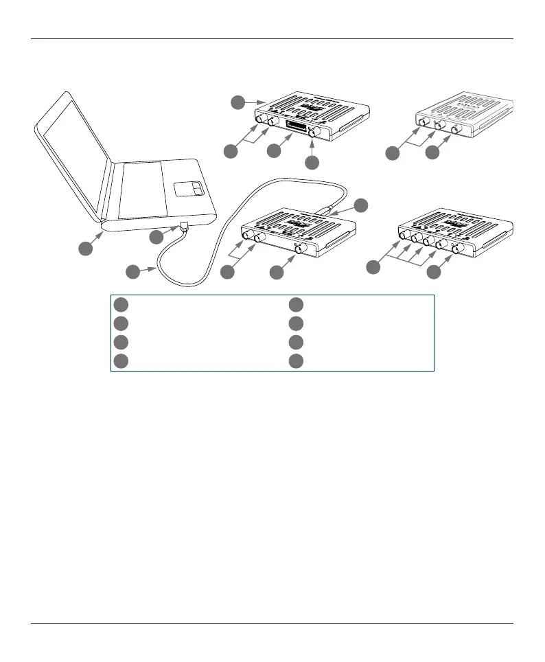
Step 3: Connect your oscilloscope
1. Connect the oscilloscope to your PC using the USB cable supplied, as shown in the connection
diagram below.
b
b
d
d
c
b
a
d
b
d
e
h
f
g
a
PicoScope PC Oscilloscope
e
Oscilloscope USB port
b
Analog input channels
f
Pico USB cable
c
Digital input channels
g
PC USB port
d
AWG output BNC
h
PC
2. Wait for your computer to install the oscilloscope. While doing so it will display a message or
icon in the task bar telling you it has found the device.
3. Run the PicoScope software.
4. If you wish to use a probe, connect one to Channel A. Touching the metal tip of the probe
should cause a small 50 or 60 hertz signal to appear in the PicoScope window.
Once you have nished the basic installation, the PicoScope 6 User’s Guide will provide further
information about setting up and using your oscilloscope.
 Loading...