- 2 -
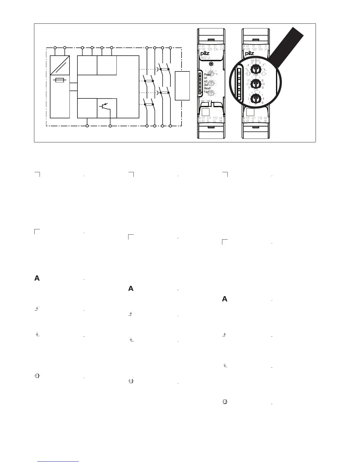
Blockschaltbild/Klemmenbelegung Block diagram/terminal configuration Schéma de principe
*nur bei U
B
= 48 – 240 V AC/DC * only when U
B
= 48 – 240 VAC/DC * uniquement pour U
B
= 48 à 240 V AC
566336011
Mitte: Frontansicht mit Abdeckung
Rechts: Frontansicht ohne Abdeckung
Centre: Front view with cover
Right: Front view without cover
Schéma du milieu : vue frontale avec capot de
protection
A droite : vue frontale sans capot de protection
Funktionsbeschreibung
547279627
` Einkanaliger Betrieb: keine Redundanz
im Eingangskreis, Erdschlüsse im Start-
kreis und Eingangskreis werden erkannt.
` Zweikanaliger Betrieb ohne Querschlus-
serkennung: redundanter Eingangskreis,
erkennt
– Erdschlüsse im Start- und Eingangs-
kreis,
– Kurzschlüsse im Eingangskreis und
bei überwachtem Start auch im Start-
kreis.
550687755
` Zweikanaliger Betrieb mit Querschlus-
serkennung: redundanter Eingangskreis,
erkennt
– Erdschlüsse im Start- und Eingangs-
kreis,
– Kurzschlüsse im Eingangskreis und
bei überwachtem Start auch im Start-
kreis,
– Querschlüsse im Eingangskreis.
550690059
` Automatischer Start: Gerät wird aktiv,
nachdem Eingangskreis geschlossen
wurde.
` Manueller Start: Gerät wird aktiv, wenn
der Eingangskreis geschlossen ist und
danach der Startkreis geschlossen wird.
463145099
` Überwachter Start mit steigender Flanke:
Gerät wird aktiv, wenn der Eingangskreis
geschlossen ist und nach Ablauf der
Wartezeit (s. techn. Daten) der Startkreis
geschlossen wird.
457338123
` Überwachter Start mit fallender Flanke:
Gerät wird aktiv, wenn
– der Eingangskreis geschlossen ist und
danach der Startkreis geschlossen
und wieder geöffnet wird.
–der Startkreis geschlossen und nach
Schließen des Eingangskreises wieder
geöffnet wird.
419458699
` Start mit Anlauftest: Das Gerät prüft, ob
nach Anlegen der Versorgungsspannung
geschlossene Schutztüren geöffnet und
wieder geschlossen werden.
1047578379
` Kontaktvervielfältigung und –verstärkung der
– unverzögerten Sicherheitskontakte durch
Anschluss eines Kontakterweiterungs-
blocks PNOZsigma über Verbindungs-
stecker
– verzögerten/unverzögerten Sicherheits-
kontakte durch Verdrahtung von Kontak-
terweiterungsblöcken oder externen
Schützen möglich
Function description
`
Single-channel operation: no redundan-
cy in the input circuit, earth faults in the
reset circuit and input circuit are detect-
ed.
` Dual-channel operation without detec-
tion of shorts across contacts: redun-
dant input circuit, detects
– earth faults in the reset and input cir-
cuit,
– short circuits in the input circuit and,
with a monitored reset, in the reset cir-
cuit too.
` Dual-channel operation with detection of
shorts across contacts: redundant input
circuit, detects
– earth faults in the reset and input cir-
cuit,
– short circuits in the input circuit and,
with a monitored reset, in the reset cir-
cuit too,
– shorts between contacts in the input
circuit.
` Automatic reset: Unit is active once the
input circuit has been closed.
` Manual reset: Unit is active once the in-
put circuit is closed and then the reset
circuit is closed.
` Monitored reset with rising edge: Unit is
active once the input circuit is closed and
once the reset circuit is closed after the
waiting period has elapsed
(see technical details).
` Monitored reset with falling edge: Unit is
active once
– the input circuit is closed and then the
reset circuit is closed and opened
again.
– the reset circuit is closed and then
opened again once the input circuit is
closed.
` Reset with start-up test: The unit checks
whether safety gates that are closed are
opened and then closed again when
supply voltage is applied.
` Ability to increase the number of contacts
available on the
– instantaneous safety contacts by using
connectors to link to a PNOZsigma con-
tact expansion module
– delayed/instantaneous safety contacts by
connecting contact expansion modules or
external contactors
Description du fonctionnement
`
Commande par 1 canal : pas de redon-
dance dans le circuit d'entrée, les mises
à la terre dans les circuits de réarmement
et d'entrée sont détectés
` 2 canaux d'entrée sans détection des
court-circuits : circuit d'entrée redon-
dant; sont détecté
– les mises à la terre dans le circuit de
réarmement et le circuit d'entrée;
– les courts-circuits dans le circuit d'en-
trée ainsi que dans le circuit de réar-
mement lors d'un réarmement auto-
contrôlé.
` 2 canaux d'entrée avec détection des
court-circuits : circuit d'entrée redon-
dant; sont détectés
– les mises à la terre dans le circuit de
réarmement et le circuit d'entrée;
– les courts-circuits dans le circuit d'en-
trée ainsi que dans le circuit de réar-
mement lors d'un réarmement auto-
contrôlé;
– les courts-circuits entre les circuits
d'entrée.
` Réarmement automatique : l'appareil est
activé une fois que le circuit d'entrée est
fermé.
` Réarmement manuel : l'appareil est acti-
vé lorsque le circuit d'entrée est fermé et
après que le circuit de réarmement se
soit fermé.
` Réarmement auto-contrôlé avec front
montant : l'appareil est activé lorsque le
circuit d'entrée est fermé et lorsque le
circuit de réarmement se ferme après
l'écoulement du temps d'attente (voir les
caractéristiques techniques).
` Réarmement auto-contrôlé avec front
descendant : l'appareil est actif si
– le circuit d'entrée est fermé puis le cir-
cuit de réarmement fermé et réouvert.
– le circuit de réarmement est fermé
puis réouvert après la fermeture du cir-
cuit d'entrée.
` Réarmement avec test des conditions in-
itiales : l'appareil contrôle, après l'appli-
cation de la tension d'alimentation, si les
protecteurs mobiles fermés sont ouverts
puis refermés.
InputInput
A1 A2
K1
K2
13 23
14 24
S21 S22
=
Power
K3
K4
37 47
38 48
Reset/
Start
S34
S11 S12
=
Y32
(~)*
Interface
expansion
unit
( )*
In2+
In2-
In2+
In2-
In2+
In2-

 Loading...


