- 3 -
Wird nach EN 60204-1 Abs.: 9.4.3.1 die
Phase Li(-) der Versorgungsspannung auf
Erdpotenzial gelegt, werden Erdschlüsse er-
kannt. Bei Erdschlüssen im Eingangs-, Start-
oder Rückführkreis löst der Fehlerstrom
(I
F
i>i1,2iA) die interne elektronische Siche-
rung aus und die Ausgangsrelais fallen ab.
Betriebsarten
• Einkanaliger Betrieb
- ein Eingangskreis wirkt auf beide Kanäle
- keine Redundanz (Ausfallsicherheit) im
Eingangskreis
• Zweikanaliger Betrieb
- zwei redundante (d. h. identische) Ein-
gangskreise wirken auf Kanal 1 und
Kanal 2
- Überwachung der Kontakte im Ein-
gangskreis (Ausfallsicherheit gegen
Kurzschluss)
• Manueller Start
- Ansteuerung des Startkreises mit
Starttaster oder Startkontakt
• Automatischer Start
- die Ausgangsrelais ziehen an, sobald
die Eingangskreise geschlossen sind
- für NOT-AUS-Stromkreise ist diese Be-
triebsart nicht zulässig, da die Anlage
nach Spannungsausfall und -wiederkehr
selbsttätig anläuft.
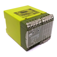
Montage
Das Gerät muss in einen Schaltschrank mit
einer Schutzart von mind. IP 54 eingebaut
werden. Zur Befestigung auf einer Norm-
schiene hat das Gerät ein Rastelement auf
der Rückseite.
Sichern Sie das Gerät bei Montage auf einer
senkrechten Tragschiene (35 mm) durch ein
Halteelement wie z. B. Endhalter oder
Endwinkel.
Inbetriebnahme
Beachten Sie bei der Inbetriebnahme:
• Vor die Ausgangskontakte eine
Sicherung (10 A flink oder 6 A träge)
schalten, um das Verschweißen der
Kontakte zu verhindern.
• Keine kleinen Ströme (z. B. 30 mA) mit
Kontakten schalten, über die zuvor große
Ströme geführt wurden.
• Hilfskontakt 41-42 nicht für Sicherheits-
stromkreise verwenden!
• max. zulässige Leitungslängen:
Eingangskreis zweikanalig
max. Leitungslänge DC: 3,5 km
max. Leitungswiderstand DC: 100 Ω
Eingangskreis einkanalig
max. Leitungslänge DC: 1,75 km
max. Leitungswiderstand DC: 50 Ω
Voraussetzungen:
Leiterquerschnitt 2 x 1,5 mm²
Kapazität 150 nF/km
Widerstand 28 Ω/km
Temperatur max. 25 °C
• Leitungsmaterial aus Kupferdraht mit einer
Temperaturbeständigkeit von 60/75 °C
verwenden.
• Das Anzugsdrehmoment der Schrauben
auf den Anschlussklemmen darf max.
1,2 Nm betragen.
• Angaben im Kapitel "Technische Daten"
unbedingt einhalten.
If phase L(-) of the operating voltage is
connected to the earth potential according
to EN 60204-1 par. 9.4.3.1, earth faults are
detected. In the case of an earth fault in the
input circuit, reset circuit or feedback
control loop, the fault current (I
F
i>i1,2iA)
triggers the internal electronic fuse F1 and
the output relays de-energise.
Operating modes
• Single channel operation
- one input circuit operates both
channels
- no redundancy (fail-safe) in the input
circuit
• Two channel operation
- two redundant (i.e. identical) input
circuits operate channel 1 and channel 2
- monitoring of the contacts in the input
circuit (fail-safety in the event of short
circuit)
• Manual reset
- Control of a reset circuit with a reset
button or a reset contact
• Automatic reset
- the output contacts energise as soon
as the input circuit is closed
- this mode of operation is not
permissable for Emergency Stop
circuits as the installation is activated
independently following a loss/return of
supply voltage
Installation
The unit must be panel mounted (min. IP
54). There is a notch on the rear of the unit
for DIN-Rail attachment.
If the unit is installed on a vertical mounting
rail (35 mm), ensure it is secured using a
fixing bracket such as end bracket.
Operation
Please note for operation:
• To prevent a welding together of the
contacts, a fuse (10 A quick or 6 A
slow acting) must be connected
before the output contacts.
• Low currents (e.g. 30 mA) should not be
switched across contacts across which
high currents have previously been
switched.
• Auxilliary contact 41-42 are not to be
used for safety circuits.
• max. cable runs:
Input circuit two channel
Max. cable run DC: 3.5 km
Max. resistance DC: 100 Ω
Input circuit single channel
Max. cable run DC: 1.75 km
Max. resistance DC: 50 Ω
Requirements:
Cable 2 x 1.5 mm²
Capacitance 150 nF/km
Resistance 28 Ω/km
Temperature max. 25 °C
• Use copper wiring that will withstand
60/75 °C
• Tighten terminals to 1.2 Nm.
• Important details in the section „Technical
Data“ should be noted and adhered to.
Lorsque la phase (L-) de la tension
d'alimentation est mise à la masse d'après
EN 60204-1 § 9.4.3.1, un défaut de masse
est détecté. Lorsqu'il y a des défauts de
masse dans les canaux d'entrée, de
validation ou dans la boucle de retour, le
fusible électronique F1 interne se déclenche
(I
F
>1,2iA) et les relais de sortie retombent.
Mode de fonctionnement
• Commande par un canal
- Le circuit d'entrée agit sur les deux
canaux.
- Pas de redondance dans les canaux
d'entrée .
• Commande par deux canaux
- deux circuits d'entrée redondants (c.à.d
identiques) agissent sur les canaux 1 et
2.
- Surveillance des contacts dans les
circuits d'entrée (détection de la
défaillance d'un contact de l'AU)
• Réarmement manuel
- réarmement par bouton poussoir ou
contact externe .
• Réarmement automatique
- les relais de sortie montent dès que les
canaux d'entrée sont fermés.
- Attention ! En cas de réarmement
automatique, la montée du relais ne doit
pas remettre votre installation sous
tension.
Montage
Le relais doit être installé dans une armoire
équipée d'une protection IP 54. Sa face
arrière permet un montage sur rail DIN.
Immobilisez l'appareil monté sur un rail DIN
vertical (35 mm) à l'aide d'un élément de
maintien comme par ex. un support ou une
équerre terminale.
Mise en oeuvre
Remarques préliminaires :
• Protection des contacts de sortie par
des fusibles 10 A rapides ou 6 A
normaux pour éviter leur soudage.
• Ne pas commuter de petites intensités
(par ex. 30 mA) avec des contacts qui
ont précédemment coupé de fortes
intensités.
• Ne pas utiliser le contact de signalisation
41-42 pour les circuits de sécurité.
• Longueurs de câble max. admissibles :
Circuit d'entrée commandé par 2
canaux
Longueur de câble max. DC : 3,5 km
Résistivité max. DC : 100 Ω
Circuit d'entrée commandé par 1 canal
Longueur de câble max. DC : 1,75 km
Résistivité max. DC : 50 Ω
Préalable :
Câble 2 x 1,5 mm
2
Capacité 150 nF/km
Résistivité 28 Ω/km
Température max. 25°C
• Utiliser uniquement des fils de cablâge en
cuivre 60/75 °C.
• Le couple de serrage sur les bornes de
raccordement ne doît pas dépasser
1,2 Nm.
• Respecter les données indiquées dans le
chapitre "Caractéristiques techniques".

 Loading...