Functiondescription
OperatingManualPNOZmc7p
1003050EN02
10
4 Functiondescription
4.1 Functions
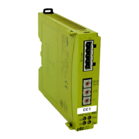
ThevirtualinputsandoutputsthataretobetransferredviathefieldbusCCLinkareselec
tedandconfiguredinthePNOZmultiConfigurator.Thebaseunitandthefieldbusmodule
PNOZmc7pareconnectedviaajumper.Thefieldbusmoduleisalsosuppliedwithvoltage
viathisjumper.AfterthesupplyvoltageisswitchedonorthecontrolsystemPNOZmultiis
reset,thefieldbusmodulePNOZmc7pisconfiguredandstartedautomatically.
LEDsindicatethestatusofthefieldbusmoduleonthefieldbusCCLink.
TheconfigurationisdescribedindetailinthePNOZmultiConfigurator'sonlinehelp.
4.2 Inputandoutputdata
Thedataisstructuredasfollows:
} Inputarea
– InputsonPNOZmultiConfigurator:i00…i23
– InputdataCCLink:RYn,RY1nwithn=0…F
Example:i23>RY17
s F L B C B A 9 8 7 6 5 4 3 2 1 0
RY0n i15 i14 i13 i12 i11 i10 i09 i08 i07 i06 i05 i04 i03 i02 i01 i00
RY1n i23 i22 i21 i20 i19 i18 i17 i16
} Outputarea
– OutputsonPNOZmultiConfigurator:o00…o23
– OutputdataCCLink:RXn,RX1nwithn=0…F
Example:o22>Rx16
s F L B C B A 9 8 7 6 5 4 3 2 1 0
RX0n o15 o14 o13 o12 o11 o10 o09 o08 o07 o06 o05 o04 o03 o02 o01 o00
RX1n o23 o22 o21 o20 o19 o18 o17 o16
Detailedinformationondataexchangeisavailableinthedocument"CommunicationInter
faces"inthesectionentitled"Fieldbusmodules".
Thenumberofvirtualinputsandoutputscanbeextendedto128(seedocument"Commu
nicationInterfaces"inthesectionentitled"Fieldbusmodules")
INFORMATION
WhenpollingthetablesandsegmentsofthePNOZmulti,pleasenotethat
communicationontheCCLinkisviatheRegister.

 Loading...