Installation
OperatingManualPNOZmc7p
1003050EN02
12
5 Installation
5.1 Generalinstallationguidelines
} Thecontrolsystemshouldbeinstalledinacontrolcabinetwithaprotectiontypeofat
leastIP54.Fitthecontrolsystemtoahorizontalmountingrail.Theventingslotsmust
faceupwardanddownward.Othermountingpositionscoulddestroythecontrolsystem.
} Usethenotchesontherearoftheunittoattachittoamountingrail.Connectthecon
trolsystemtothemountingrailinanuprightposition,sothattheearthingspringsonthe
controlsystemarepressedontothemountingrail.
} TheambienttemperatureofthePNOZmultiunitsinthecontrolcabinetmustnotexceed
thefigurestatedinthetechnicaldetails,otherwiseairconditioningwillberequired.
} TocomplywithEMCrequirements,themountingrailmusthavealowimpedancecon
nectiontothecontrolcabinethousing.
CAUTION!
Damageduetoelectrostaticdischarge!
Electrostaticdischargecandamagecomponents.Ensureagainstdischarge
beforetouchingtheproduct,e.g.bytouchinganearthed,conductivesur
faceorbywearinganearthedarmband.
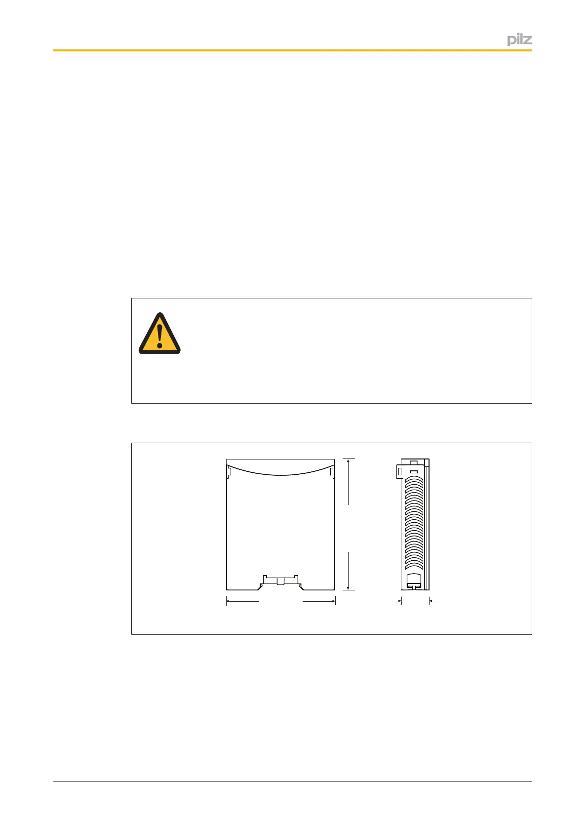
5.2 Dimensions
94 (3.70")
22,5
(0.88")
114 (4.49")
5.3 Connectingthebaseunitandexpansionmodules
Youcaninstallamaximumof1PNOZmc7ptotheleftofthebaseunit.
} Donotconnectaterminatortothelastexpansionmoduleonthelefthandside.
} InstalltheexpansionmoduleinthepositioninwhichitisconfiguredinthePNOZmulti
Configurator.
 Loading...