Installation
Operating Manual PSEN ml b 1.1/2.1/2.2
1003884-EN-12
| 35
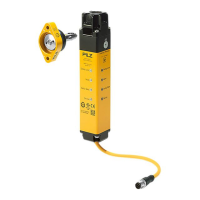
8.3 Installation safety switch
} To fix the safety switch at the three possible mounting positions, there are three drill holes
on three sides.
As a result, the safety switch can be installed on the frames of left and right hinged sliding
gates and swing gates. If necessary use a Mounting plate [ 36] or Mounting
bracket [ 38] (see Order reference: Accessories [ 75]).
Different holding forces arise, based on the installation.
– Fixing screws in parallel to actuator:
Holding forceF
Zh
=7.500 N,
Holding forceF
1max
in accordance withENISO14119=15.000 N
– Fixing screws side-on to actuator:
Holding forceF
Zh
=5.000 N,
Holding forceF
1max
in accordance withENISO14119=10.000 N
INFORMATION
The specified holding forces only apply to installation without mounting
bracket. The holding forces when installed with a mounting bracket can be
found in the table "Technical details for mounting bracket [ 72]".
The tapped holes must have a depth of at least 6 mm.
Installation of safety switch Tapped hole
Fixing screws in parallel/side-on to actuator,
no mounting plate
Tapped holes for four M5 screws on the
mounting surface.
Fixing screws in parallel/side-on to actuator,
with mounting plate
Tapped holes for two M8 screws on the
mounting surface, for attaching the mount-
ing plate.
Fixing screws crosswise to actuator with L-
bracket
Tapped holes for two M6 screws on the
mounting surface, for attaching the mount-
ing surface
 Loading...