Force Security System - Installation Guide
10
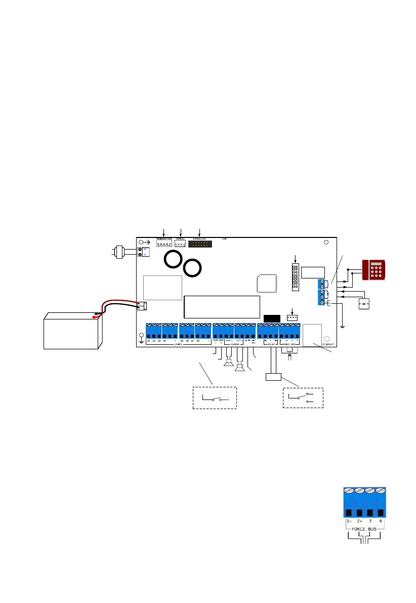
8. Force BUS. All expanders and keypads have the same 1-4 wire numbering.
9. Ethernet socket (RJ-45)
10. Technician keypad’s connector
11. Earth ground - use only with non-PIMA non-metal cases!
12. Telephone line
13. Telephone set, fax, answering machine
14. GSM add-on socket
15. For future use
16. Serial RS-232 socket
17. Radio transmitter socket
18. 14-20 VAC input
19. Backup battery, Red (+)/Black (-)
2.4 Connecting expanders and peripherals
Figure 4. Wiring diagram
2.5 The BUS
The BUS is a serial communication channel, used for exchanging data between the control
panel and the peripherals. The protocol in use by the BUS is ForceBUS (PIMA proprietary).
Use four 0.5mm (24 Gauge (AWG)) wires. The maximum BUS length is 500m,
including all peripherals and keypads.
Connect the wires using the numbers 1-4, where terminal #1 on the control
panel connects to the same terminal on the peripheral, and so on.
BATTERY
12V/7.0Ah
Maximum battery
charge current: 500mA
-
+
AC
Tamper 2
External
Siren
Internal
Siren
Ethernet Socket
Telephone
socket
Telephone set/Fax/
Answering machine
Technician keypad and
local expander socket
GSM add-on
socket
Caution: High Voltage!
Disconnect all sources of power
supply prior to installation
For future use
Serial
RS-232
Radio
Transmitter
230VAC, 16.5VAC
Do not connect the
transformer to
receptacle controlled
by a switch
(-) BLK
(+) RED
ON/OFF
output
Alarm
output
(-)
(-)
Relay
output
Device
BUS cable. Connection to
keypads and expanders
Tamper 1*
Zone Inputs
50-60Hz
Primary
Earth
ground
NC
Relay
COM
NO
TMPR 1-2
Tamper switch
* Control panel’s
enclosure tamper