Force Security System - Installation Guide
14
Card location buzzer
Supplied mounted in a standard plastic 19 X 13 cm box
Size: 8.2 X 15cm
Technical specs: 10-15V, 30mA in idle state, fuse: 0.9A
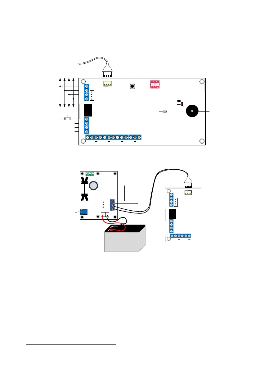
Figure 12. ZEX508 connection diagram
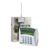
Figure 13. ZEX508 with PS-2 power supply (up to 1.2A)
connection diagram
2.9.4 Setting the expander’s ID number
Each remote expansion card must carry a unique ID number, between 1 & 16. The ID is set by
a dip-switch. Numbering must follow the next rules:
The number must be unique
Numbers must be consecutive
Each 16-zone expander (ZEX516) takes 2 consecutive numbers automatically. For example,
expander with ID number 4 takes no’s 4 & 5, so the next expander must carry the ID
number of 6.
The battery is for illustration purpose only.
POWER SUPPLY
ID
1
+
2 3 4 5 6 7 8
1(-) 2(+) 3 4
ForceBus
TAMPER
RELAY 1
NC Com NO
Int Tamper
Disconnect
RUN
BUS
(-)
1 2 3 4
1
2
3
4
To Control Panel
and other
Peripherals (BUS)
External
Tamper Input
Relay #1
Output
Zone Inputs and Aux. Voltage
RUN LED
BUS LED
Tamper
Jumper
Box Mounting
Hole
To PS-2
Power Supply
Buzzer
Technician
Keypad
Connector
Tamper Switch
Expander’s ID
Dip Switch
NC
Com
NO
AC OK
LOW BATT
+ 13 .8V
GND
16VAC
Input
PS-2
BATT
AC Status
Output
Low Battery
Status Output
Backup Battery
12V, 7Ah
POWER SUPPLY
1
+
2 3
1(-) 2(+) 3 4
ForceBus
TAMPER
RELAY 1
NC Com NO
ZEX508
+13.8VDC