Chap. 2: Installation & Wiring
9
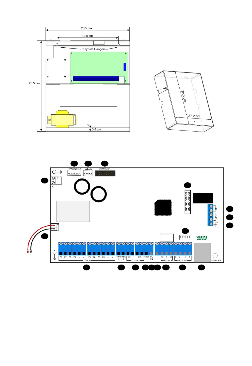
Figure 1. The control panel’s rack
Figure 2. The rack’s cover
2.3 The control panel
Figure 3. The control panel
Following is the list of the control panel’s terminals:
1. Zone inputs Z1-Z8, detectors voltage (+)/(-)
2. Tamper switches 1-2 inputs
3. External/internal Sirens, (+)/(-)
4. ALRM output (by default, switched to (-) at alarm)
5. ON/OFF output: (by default, switched to (-) on arming)
6. GND (-)
7. Relay output: NC (Normally Close), C (Common), NO (Normally Open)
11
10
12
13
14
151617
18
19
1 2 3 4 5 6 7 8 9