7
Wiring up
Install all cables with care. See illustrations on appendix for connection diagram.
Do not cut non-assigned wires. Instead, wind them together and secure to one side. They may be required
for retrofitting additional functions.
Power it up
Power supply cable
Cable colour Connection
Yellow (Battery) +12 permanent positive terminal
Red (ACC) +12 ignition positive/accessory contact
Black Earth/GND
Only connect electrical signals to suitable connecting points in the vehicle.
Connect the yellow lead of the power supply cable to the 12V permanent positive.
Connect the red lead of the power supply cable to the 12V ignition positive (accessory contact/ACC).
Connect the black lead to earth.
Insert power supply cable plug into the “POWER SUPPLY” socket of the DVB-T receiver. Ensure that
the plug latch is engaged.
Displaying & Communicating
DVB-T tuner to external Display
Connect the monitor lead from the RCA input jacks of the Display to the AV output (“AUDIO OUT L/R”
and “VIDEO OUT”) of the tuner.
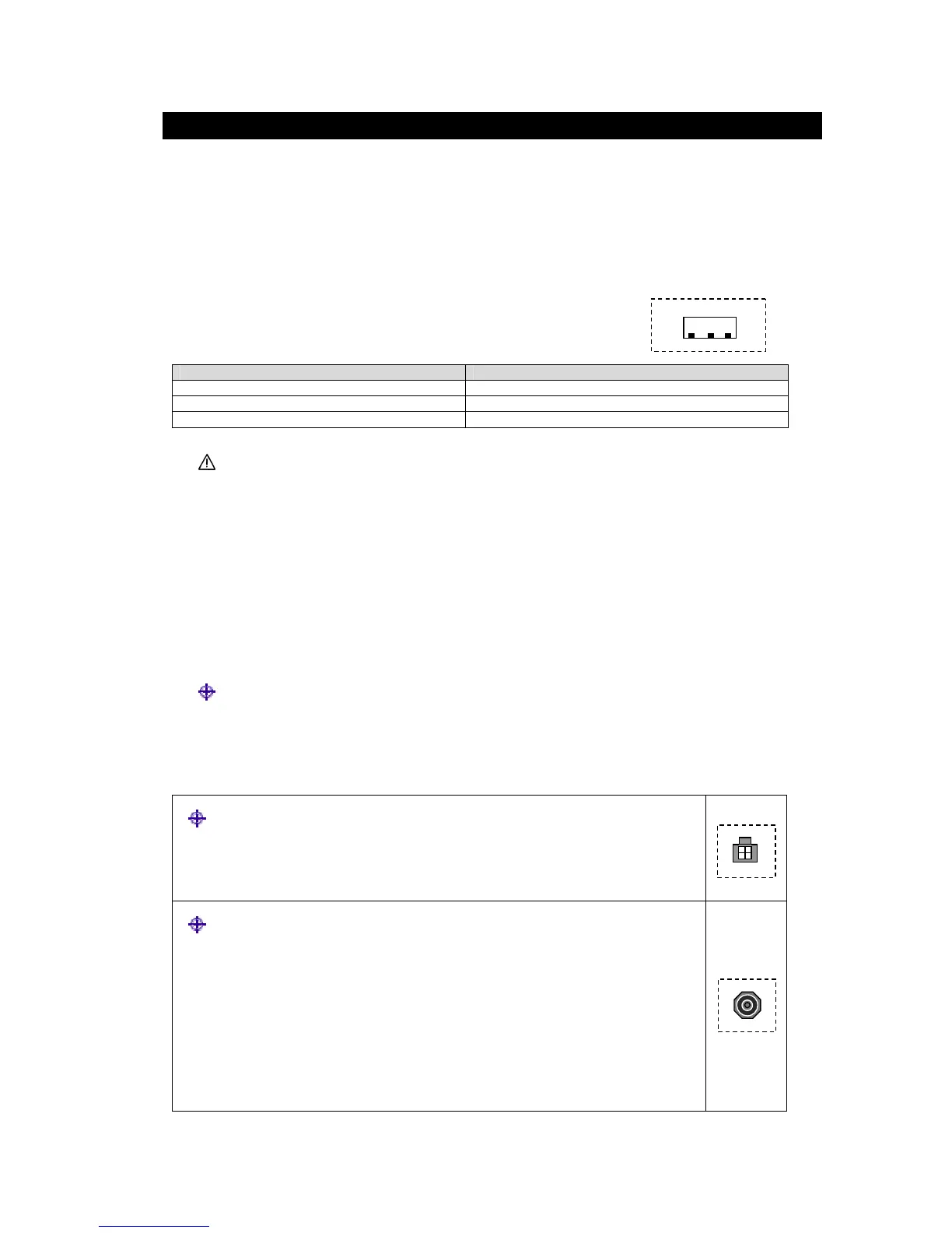
TV antennas
Up to 2 antennae can be connected to the tuner via antenna sockets “ANT IN 1” and
“ANT IN 2”
If passive antenna is use, switch the phantom supply (DC 5V) to off.
If active antenna is use, switch the phantom supply (DC 5V) to on.
Note: for assembly details please see installation instruction for antenna (supplied with
the antenna).
 Loading...