12
10.
MOUNTING BACK HANDLE TO THE
UPPER SMOKER CABINET ASSEMBLY
Parts Required:
1 x Upper Smoker Cabinet Assembly (#2)
1 x Back Handle (#3)
4 x 1/4-20*5/8”(#A)
Installation:
• Mount Back Handle (#3) to the Upper
Smoker Cabinet Assembly (#2) using 4 x
1/4-20*5/8”(#A) as Fig.10 shown.
Fig.10
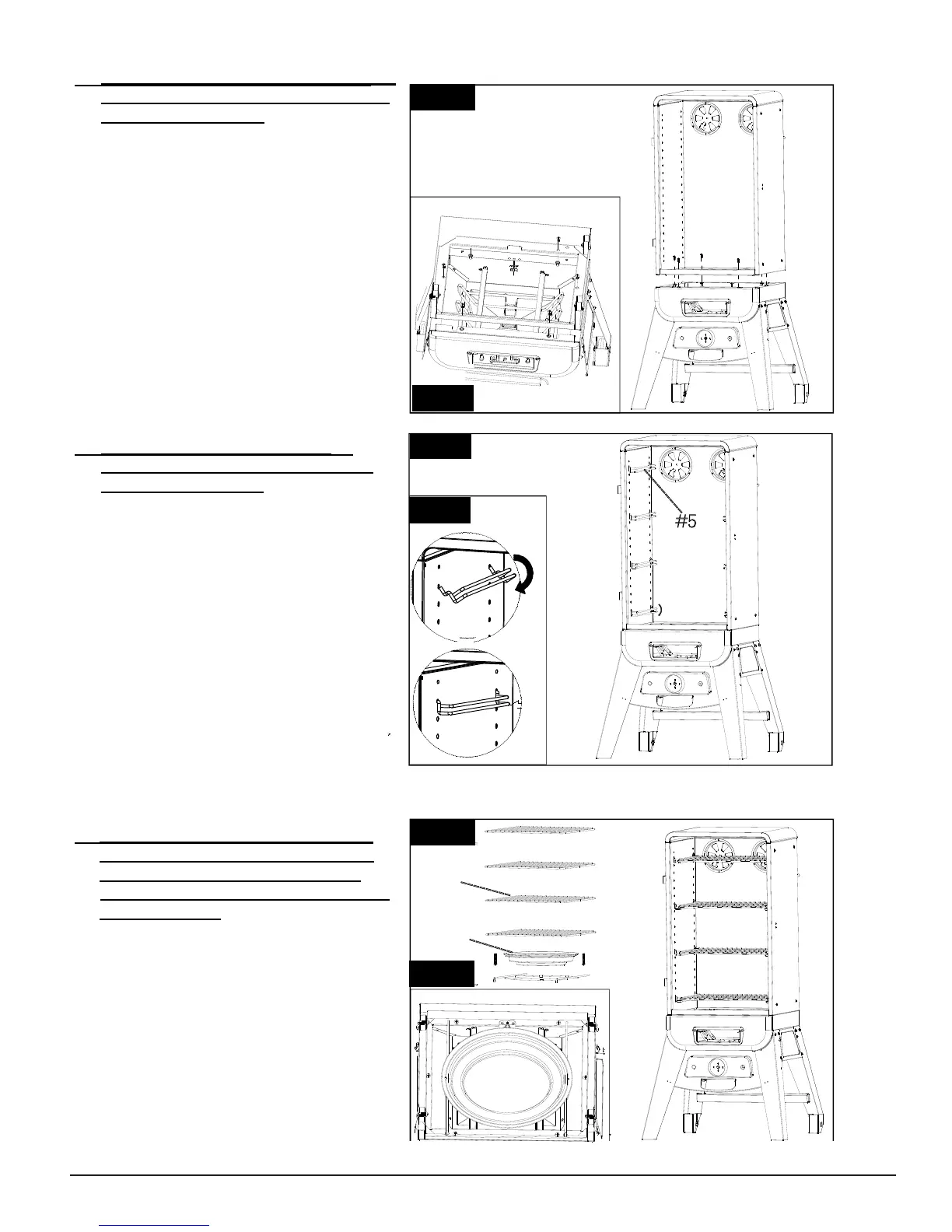
11.
MOUNTING UPPER SMOKER CABINET
ASSEMBLY TO THE LOWER SMOKER
CABINET ASSEMBLY
Parts Required:
1 x Upper Smoker Cabinet Assembly (#2)
1 x Lower Smoker Cabinet Assembly (#9)
1 x Temperature Sensor Bracket (#27)
6 x #10-24*1/2”(#C) & 2x #5-32*1/2”(#F)
Installation:
• Mount Upper Smoker Cabinet Assembly
(#2) to the Lower Smoker Cabinet Assembly
(#9) using 6 x #10-24*1/2”(#C) and 2 x #5-32
*1/2” Screw (#F) as Fig.11.1 & Fig.11.2 shown.
Note: Assemble all (6) screws, align the
Upper Cabinet to the Lower Cabinet then
tighten all screws as Fig 11.1 and Fig 11.2
shown. Please also take out the heating
element mounting bracket by lossing two
screws as Fig.11.4
• Mount temperature sensor probe with
Temperature Sensor Bracket (#27) to extend
above the lip of the Lower Cabinet using 2 x
# #5-32*1/2” Screw (#G) as Fig. 11.3 shown.
12.
ASSEMBLING COOKING GRID
SUPPORT TO THE UPPER SMOKER
CABINET ASSEMBLY
Parts Required:
8 x Cooking Grid Support (#5)
1 x Upper Smoker Cabinet Assembly (#2)
Installation:
• Assemble four Cooking Grid Supports
(#5)in the holes in the left side of the smoker.
Repeat the procedure for the right side
making sure the Cooking Grid Support (#2)
on the left side and right side are at the same
height as Fig.13 shown, so the Cooking Grids
are level.
Fig.12
#3
--
---
------
---
---
#5
----------
Fig.11.1
Fig.11.2
Fig.11.3
-
-
-
-
-
-
-
-
-
-
-
-
-
-
-
-
-
-
-
-
-
-
-
-
-
-
-
-
-
-
-
-
-
-
-
-
-
-
-
-
-
-
-
-
-
-
-
-
Fig.11.4