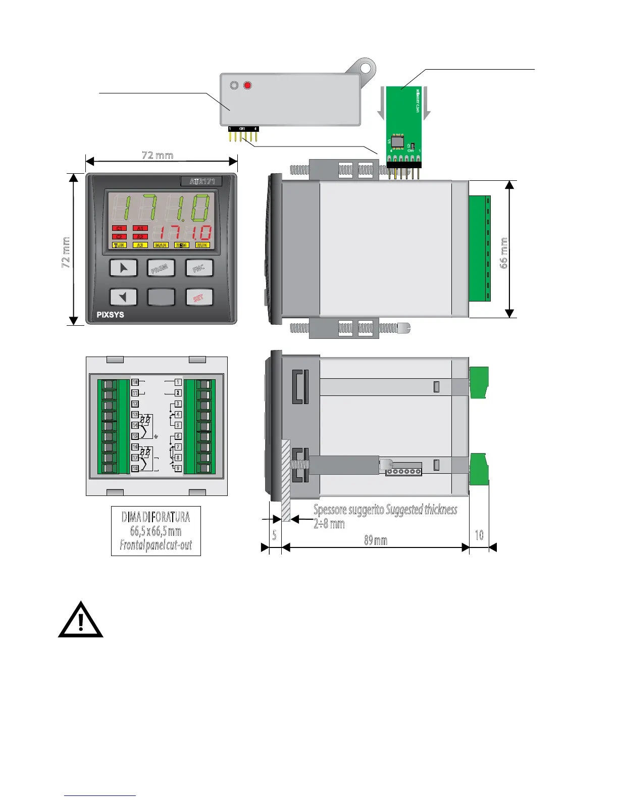
EasyManua.ls Logo

Pixsys ATR 171 - Dimension and installation; Electrical connections

Pixsys ATR 171
92 pages
To Next Page IconTo Next Page
To Previous Page IconTo Previous Page
Loading...
User manual - ATR171 7
4 Dimension and installation
ATR171
FNC
PRGM
SET
C1
A1
C2
A2
TUN
A3
MAN
REM
RUN
1
2
3
4
5
6
7
8
9
SUPPLY
24...230V
AC/DC
SSR/V
mA
+
-
ATR171-23ABC-T
10
11
12
13
14
15
16
17
18
+Vdc
Q1
8A
230V
1/2HP
+
-
TC
485+
485-
+
-
TC
AI1
V
mA
Q2
8A
230V
1/2HP
Q3
8A
230V
1/2HP
AI2
CN1
1 6
16
Memory Card
U1
C1
CN1
16
MEMORY C.241
DIMA DI FORATURA
66,5 x 66,5 mm
Frontal panel cut-out
89 mm
5 10
66 mm
72 mm
72 mm
Spessore suggerito Suggested thickness
2÷8 mm
42mm
insert / inserimento
Memory Card
Memory Card (optional)
Cod. MEMORY C241
Memory Card (optional)
with battery Cod. MEMORY C243
5 Electrical connections
Even though this instrument has been designed to withstand the most
heavy-duty disturbances in industrial environments, the following
precautions should be taken:
Distinguish the supply line from the power lines.
Keep contactor units, electromagnetic contactors and high power motors away
from each other and anyway use specific filters.
Keep power units away from each other, especially if with phase control.

Table of Contents

Related product manuals