14 ATR171 - User manual
6 Display and keys functions
ATR171
FNC
PRGM
SET
C1
A1
C2
A2
TUN
A3
MAN
REM
RUN
C1
A1
C2
A2
TUN
A3
MAN
REM
RUN
1
3
4
7
26 5
9 8 10
1613 14
12 15
11
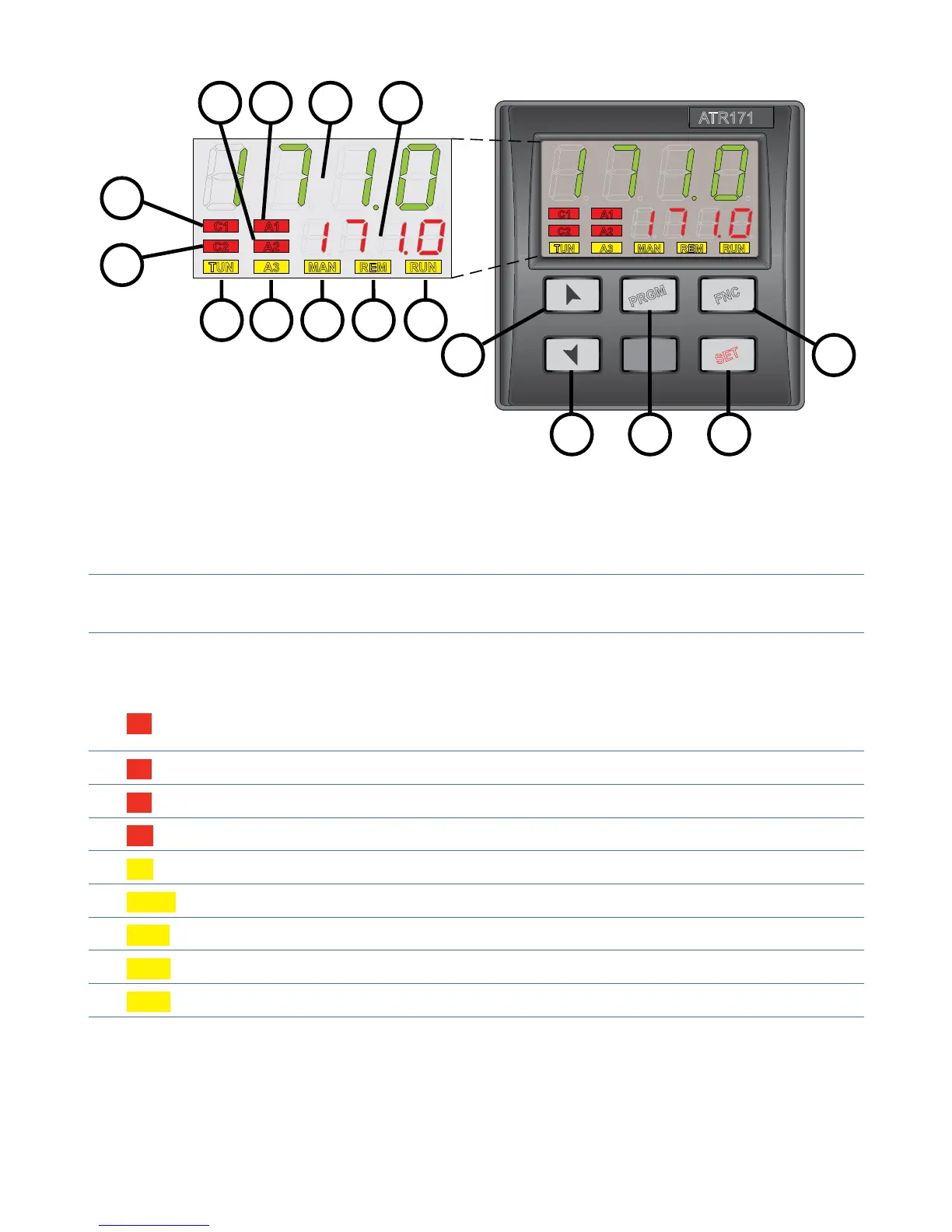
6.1 Numeric indicators (Display)
1
1234
Normally displays the process. During the configuration phase, it
displays the parameter being inserted.
2
1234
Normally displays the setpoint. During the configuration phase, it
displays the parameter value being inserted.
6.2 Meaning of Status Lights (Led)
3 C1
On when command output is active. For open / close logic: on
during valve opening.
4
C2 For open/ close logic: on during valve closing.
5
A1 On when alarm 1 is active.
6
A2 On when alarm 2 is active.
7
A3 On when alarm 3 is active.
8
MAN On when “Manual” function is active.
9
TUN On when controller is executing an auto-tuning cycle.
10
REM On when serial communication is in progress.
11
RUN On when counting of Timer function is active.