5
2.2 Switch Front Panel Layout
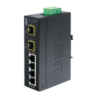
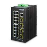
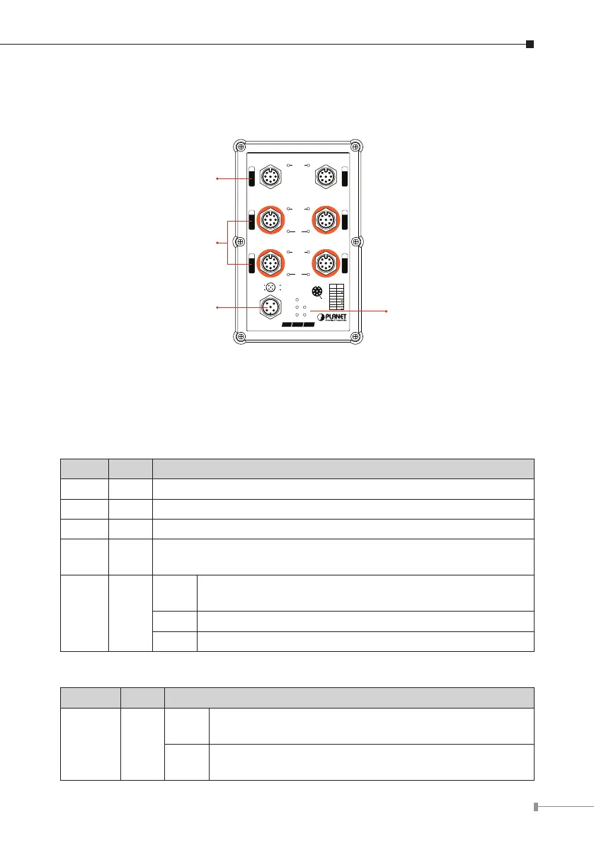
Figure 2-1 shows the front panel of the Industrial Managed Switch.
LNK/ACT
LNK/ACT
PoE
LNK/ACT
PoE
FAULT
PWR
2
PWR
1
R.O.
Ring
V2
V2
V1
V1
INPUT
DC 48-56V
1
3
5
2
4
6
12
5
64
8
73
Pin Con
1 DA+
2 DA
5 DC
8 DD
3 DB+
6 DB
7 DD+
4 DC+
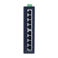
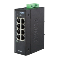
IGS-604HPT-M12
IP67PoE Mgt.
M12 Gigabit
Ethernet Port
M12 Power
Input Connector
Power, Fault,
Ring LEDs
M12 Gigabit
Ethernet
PoE+ Port
Figure 2-2: IGS-604HPT-M12 Front Panel
2.3 LED Indicators
System
LED Color Function
PWR 1 Green Lights to indicate DC power input 1 has power.
PWR 2 Green Lights to indicate DC power input 2 has power.
Fault Red Lights to indicate that the Industrial Switch has failed
Ring Green
Lights to indicate that the ERPS Ring has been created
successfully.
R.O. Green
Lights
To indicate the Ring Owner has been enabled and the
state is in idle mode.
Blinks To indicate the Ring state is in protect mode.
Off To indicate that the Ring Owner hasn’t been enabled.
Per 10/100/1000BASE-T Port (Port 1~2)
LED Color Function
LNK/ACT Green
Lights
To indicate the port is running in 10/10/1000Mbps
speed and successfully established.
Blinks
To indicate the switch is actively sending or receiving
data over that port.
 Loading...